Sign In
Upload
Manuals
Brands
Canon Manuals
All in One Printer
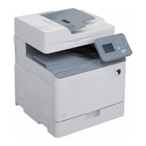
imageRUNNER C1335 Series
Canon imageRUNNER C1335 Series Manuals
Manuals and User Guides for Canon imageRUNNER C1335 Series. We have
1
Canon imageRUNNER C1335 Series manual available for free PDF download: Service Manual
Canon imageRUNNER C1335 Series Service Manual (607 pages)
Brand:
Canon
| Category:
All in One Printer
| Size: 38.82 MB
Table of Contents
Table of Contents
4
Safety Precautions
9
Laser Safety
10
Handling of Laser System
10
Turn Power Switch
11
Power Supply
11
Safety of Toner
12
About Toner
12
Toner on Clothing or Skin
12
Notes When Handling a Lithium Battery
12
Notes before Servicing
12
Points to Note at Cleaning
12
Notes on Assembly/Disassembly
13
Points to Note When Tightening a Screw
13
1 Product Overview
14
Product Lineup
14
Host Machine
15
Option ---------------------------------------------------------------------------------
16
Features
18
Product Features
18
Specifications
19
Weight and Size
19
Productivity (Print Speed)
20
Paper Type
21
Parts Name
24
External View
24
Cross Sectional View
27
Operation
28
Power Switch
28
Control Panel
29
Main Menu
30
2 Technical Explanation
32
Basic Configuration
32
Functional Configuration
33
Original Exposure and Feed System
34
Construction
34
Basic Operation
37
Reader Unit Controls
44
Original Detection
44
Image Processing
45
Shading Correction
48
Control of ADF
51
Pickup Control
51
Original Size Detection
56
Service Tasks
57
Main Controller
58
Overview
58
Laser Exposure System
60
Overview
60
Specification
62
Various Controls
63
Execution Timing
63
Service Tasks
68
Image Formation System
69
Overview
69
Print Process
70
Controls
72
Developing Bias Control
74
Atvc Control
79
Itb Cleaning
82
Drum Cleaning
84
Image Stabilization Control
84
Service Tasks
101
Fixing System
102
Overview
102
Controls
104
Print Temperature Control
106
Protection Function
115
Service Tasks
117
Pickup / Feed System
118
Overview
118
Paper Path
120
Controls
121
Registration Control
128
Paper Detection
128
Paper Size Detection
128
Delivery Assembly
129
Service Tasks
133
External Auxiliary System
134
Controls
134
Software Counter
134
Embedded RDS
139
Product Overview
139
Features and Benefits
139
Major Functions
139
Limitations
140
Service Cautions
141
E-RDS Setup
141
Faq
143
Troubleshooting
144
Error Code and Strings
146
3 Periodical Service
148
List of Periodically Replacement Parts, Consumable Parts and Locations for Cleaning
148
Periodically Replacement Parts
149
Estimated Life of Consumables
149
Consumable Parts
150
4 Disassembly/Assembly
151
Preface
151
Outline
152
Points to Note When Tightening a Screw
152
List of Parts
153
External / Internal Cover
153
List of Main Unit
156
Electrical Components
159
List of Connectors
169
External Cover/Interior System
180
Layout Drawing
180
Removing the Front Cover
183
Removing the Rear Cover 1
184
Removing the Left Upper Cover
186
Removing the Left Lower Cover
186
Removing the Right Front Cover
187
Removing the Right Rear Cover/Right Rear Lower Cover
188
Removing the Right Upper Cover
189
Removing the Right Cover Unit
191
Removing the Multi-Purpose Tray
194
Removing the Delivery Tray
195
Removing the Rear Upper Cover
195
Removing the Upper Cover
196
Removing the Control Panel Unit
197
Original Exposure/Feed System
200
Layout Drawing
200
Removing the ADF Unit
201
Removing the ADF Pickup Unit
209
Removing the ADF Separation Pad
210
Removing the ADF Pickup Feed Unit
211
Removing the ADF Feed Drive Unit
214
Opening the ADF Unit + Reader Unit
216
Removing the ADF Unit + Reader Unit
217
Removing the Copyboard Glass Unit
219
Removing the CIS Unit
223
Removing the Reader Motor
228
Controller System
230
Layout Drawing
230
Removing the Main Controller Unit
231
Removing the DC Controller PCB
234
Removing the DC Controller PCB Unit
236
Removing the Secondary Transfer High-Voltage PCB
238
Developing High-Voltage PCB Unit
238
Removing the Primary Transfer High-Voltage PCB Unit
240
Removing the Power Supply Cooling Fan
243
Removing the Low-Voltage Power Supply PCB Unit
243
Removing the Touch Panel/Control Panel CPU PCB Unit / LCD Unit
247
Removing the Fax Speaker Unit
250
Removing the Fax Unit
251
Laser Exposure System
252
Layout Drawing
252
Removing the Laser Scanner Unit
252
Image Formation System
256
Layout Drawing
256
Removing the Waste Toner Container
258
Removing the Toner Container (Y/M/C/Bk)
259
Removing the Drum Unit (Y/M/C/Bk)
259
Removing the ITB Unit
262
Removing the Registration Patch Sensor Unit
267
Removing the Secondary Transfer Outer Roller Unit
269
Removing the Secondary Transfer Outer Roller Guide Unit
270
Removing the Registration Drive Unit
273
Removing the Main Drive Unit
275
Removing the Hopper Unit (Y/M/C/Bk)
277
Removing the ITB Pressure Release Switch
280
Removing the Bottle Drive Unit (Y/M/C/Bk)
281
Removing the Toner Bottle Mount (Y/M/C/Bk)
282
Fixing System
287
Layout Drawing
287
Removing the Fixing Assembly
287
Removing the Fixing Film Unit / Pressure Roller Unit
288
Removing the Fixing Drive Unit
291
Pickup/Feed System
293
Layout Drawing
293
Removing the Right Inner Cover Unit
294
Removing the Cassette Pickup Roller/Cassette Separation Roller/Cassette Feed Roller
295
Removing the Multi-Purpose Tray Pickup Roller /Multi-Purpose Tray Separation Roller /Multi-Purpose Tray Feed Roller
299
Reassembling When the Multi-Purpose Tray Separation Roller Shaft Is Detached
303
Removing the Registration/Pickup Unit
308
Removing the Delivery/Reverse Unit
316
Removing the Cassette 1 Lifter Drive Unit
317
Removing the Cassette 1 Pickup Drive Unit
320
Cleaning Procedure
322
Layout Drawing
322
Cleaning the Copyboard Glass/Reading Glass
322
Cleaning the Dustproof Glass
322
Cleaning When Installing/Removing the ITB Unit
324
Cleaning the Registration Patch Sensor Unit
325
Cleaning the Registration Front Guide
326
Cleaning the Registration Roller/Pre-Registration Roller
327
Cleaning the Secondary Transfer Guide
328
Cleaning the Fixing Inlet Guide
330
5 Adjustment
331
Document Exposure System
331
Service Mode Backup
332
When Clearing the Reader-Related RAM Data of the Main Controller PCB
333
Original Exposure and Feed System (Reader)
334
Main Controller
345
Main Controller PCB
345
DC Controller PCB
346
Control Panel CPU Pcb/Touch Panel
346
List of Parts that Require Adjustment after Disassembly
347
Pickup Feed System
348
Setting Method When the Size Detection Patterns Are Overlapped
348
Cassette Left Edge Margin Adjustment (1St Side; Mechanical Adjsutment)
349
Cassette Left Edge Margin Adjustment (1St Side; Software Adjsutment)
351
Cassette Left Edge Margin Adjustment (2Nd Side; Software Adjsutment)
352
Multi-Purpose Tray Left Edge Margin Adjustment (1St Side; Software Adjsutment)
352
Multi-Purpose Tray Left Edge Margin Adjustment (2Nd Side; Software Adjsutment)
352
Lead-Edge Margin Adjustment (1St Side/Normal Paper)
353
Lead-Edge Margin Adjustment (2Nd Side)
353
6 Troubleshooting
354
Initial Check
354
Initial Check Items List
355
Test Print
356
Overview
356
Steps to Select the Test Print PG-TYPE
356
Image Failure
357
Category: Malfunction
364
Special Management Mode
365
Overview
365
Operational Description
365
Menu List
366
Version Upgrade
368
Overview
368
Preparation
368
System Requirements
368
Downloading System Software
369
7 Error•Jam•Alarm
372
Overview
372
Jam Code
372
Error Code
372
Error Code Details
374
Jam Code
427
Jam Type
427
Alarm Code
438
8 Service Mode
440
Service Mode Menu
441
Backing up Service Mode
441
Remote UI Service Mode
442
Function Overview
442
Copier
443
Display
443
Adjust
461
Function
511
Counter
550
Feeder
563
Adjust
563
Function
564
Fax
565
List of SSSW
565
List of MENU
566
List of NUM
566
Testmode
568
Print
568
Fax
571
9 Installation
573
How to Check this Installation Procedure
573
Symbols in the Illustration
574
Installation
574
Copy Control Interface Kit-C1
575
Points to Note at Installation
575
Checking the Contents
575
Check Items When Turning off the Main Power
575
Installation Outline Drawing
575
Installation Procedure
576
Micard Attachment Kit-A1
581
Checking the Contents
581
Points to Note at Installation
581
Check Items When Turning off the Main Power
581
Installation Outline Drawing
581
Installation Procedure
582
Copy Card Reader-F1
590
Points to Note at Installation
590
Check Items When Turning off the Main Power
590
Installation Outline Drawing
590
Checking the Contents
590
Installation Procedure
591
Special Tools
601
Advertisement
Advertisement
Related Products
Canon ImageRUNNER C1325iF
Canon ImageRUNNER C1335iF
Canon imageRUNNER C1325 Series
Canon imageRUNNER C1335iFC
Canon imageRUNNER C1028i
Canon Color imageRUNNER C1022i
Canon ImageRunner C1225
Canon C1127P
Canon C1127iF
Canon ImageRunner C1225if
Canon Categories
Printer
Digital Camera
All in One Printer
Camcorder
Scanner
More Canon Manuals
Login
Sign In
OR
Sign in with Facebook
Sign in with Google
Upload manual
Upload from disk
Upload from URL