Sign In
Upload
Manuals
Brands
Honeywell Manuals
Control Unit
ControlEdge 900 platform
Honeywell ControlEdge 900 platform Manuals
Manuals and User Guides for Honeywell ControlEdge 900 platform. We have
2
Honeywell ControlEdge 900 platform manuals available for free PDF download: Hardware Planning And Installation Manual, User Manual
Honeywell ControlEdge 900 platform Hardware Planning And Installation Manual (231 pages)
ControlEdge PLC, ControlEdge RTU
Brand:
Honeywell
| Category:
Controller
| Size: 12.91 MB
Table of Contents
Table of Contents
3
Chapter 1 - about this Guide
7
Special Terms
10
How to Use this Guide
13
Chapter 2 - Overview
13
PLC I/O Network Topology
15
Chapter 3 - Controledge PLC
15
Default Port Numbers
16
I/O Network
17
System Architecture with Non Redundant PLC-CPM
17
System Architecture with Redundant PLC-CPM
18
System Component List for Controledge 900 PLC Hardware
19
Reference about Installing Racks, EPM, Power Supply and so on
21
Control Processor Module (CPM)
22
Hardware Configuration of CPM
22
PLC-CPM Mode Switch
23
PLC-CPM Rotary Switch
24
PLC-CPM Indicators
25
LED Indications on PLC-CPM
26
Device Replacement
27
Hardware Configuration of EPM
27
Hardware Configuration of IO
27
Replacing a Non-Redundant or Unsynchronized Primary PLC-CPM
27
Replacing a Secondary PLC-CPM
29
Replacing a Primary PLC-CPM
30
Replacing an Unsynchronized Primary PLC-CPM
30
Replacing a Synchronized Primary PLC-CPM
31
Component Replacement Reference
32
Chapter 4 - Controledge UOC
33
UOC I/O Expansion Network Topology
34
HSR Ring to 900 I/O
34
Downlink I/O Network
35
Non-Redundant or Redundant Star to 900 I/O
36
Redundant Star Network
37
DLR Direct Connection to 900 I/O and EIP Devices
38
DLR ETAP Connection to 900 I/O and EIP Devices
39
Non-Redundant Star to 900 I/O and EIP Devices
41
UOC CPM to 900 I/O and EIP Devices
42
Hardware Configuration of UOC-CPM
43
Reference for Installing Racks, EPM, Power Supply and so on
43
Control Processor Module Components
44
UOC-CPM Mode Switch
45
Hardware Configuration of I/O
46
UOC-CPM Indicators
46
Replacing a Non-Redundant or Unsynchronized Primary UOC-CPM
47
Modules Types
47
Device Replacement
47
Replacing a Secondary UOC-CPM
48
Replacing a Primary UOC-CPM
49
Installation
53
Rack Options
53
Chapter 5 - Controledge 900 Common Reference Information
53
Rack Types
55
Redundant Controller Rack
58
One Slot Rack
59
I/O Rack
60
Rack Orientation and Mounting
61
Rack Dimensions with Redundant Power Supply
62
Rack Size
63
Rack Installation
64
Installation Tools
65
Site and Equipment Preparation
65
Mount Racks
66
Module Insertion
69
Assembling the Redundant Controller Rack
69
Assembling I/O Rack
73
Power Supply
77
Power Consumption Calculation for Rack Power Supply
79
Power Supply Components
79
Specification of Power Supplies
79
Environmental Considerations
81
Power Status Module
82
Expansion Processor Module
82
Serial Communication Module
84
RS485 Pin Definition
85
RS232 Pin Definition
85
Controledge 900 I/O
87
Placing I/O Modules in the Racks
87
I/O Module Installation
88
I/O Module Specification
89
Universal Input/Output Module
89
UIO Module Terminal Block
90
Universal Analog Input Module (UAI)
91
Digital Input Module (16 Channels) - AC Voltage Type
91
Digital Input Module (32 Channels) - DC Voltage Type
92
Relay Output Module (8 Channels)
92
Pulse Input/Frequency Input Module (4 Channels)
93
Analog Output Module (4 Channels)
95
Analog Output Module (8 Channels)
96
Digital Input Module-AC DC Voltage Type
97
High Level Analog Input Module (16 Channels)
97
Digital Input Module-Contact Type (16 Channel)
98
Digital Output Module (8 Channels) - AC Voltage Type
99
Digital Output Module (32 Channels) - DC Voltage Type
99
Terminal Block Euro Styles
100
Terminal Block Colors
102
Installing I/O Modules
103
Terminal Block-To-Field (Signal) Wiring
106
Wiring Rules and Recommendations
107
Wire Gauge
107
Minimum Recommended Wire Sizes
107
Routing and Securing Wires
107
Signal Grounding
108
Wire Shield Grounding
108
UIO Module Wiring
109
UIO Specification of Different Hardware Versions
110
Field Wiring for Analog Input
111
Standard 2-Wire Transmitter with UIO
112
Self-Powered 3-Wire Transmitter with System Ground
113
Self-Powered 4-Wire Transmitter
114
Self-Powered 4-Wire Sinking Type Transmitter with UIO
115
Allowable Field Wiring Resistance - UIO - Analog Input Channel
116
Field Wiring for Analog Output
116
UIO for Analog Output Specification
116
Field Wiring for Digital Input (Dry Contact)
117
Field Wiring for Digital Output
119
UIO Specification for DO
119
UIO_DO Channel Configuration
120
UIO Pins Branch for Interconnecting the DO
120
Universal Analog Input Module (UAI) Wiring
121
Typical Thermocouple Resistance in Ohms Per Double Foot @ 68 Degrees F
121
Isolation
122
RTD Inputs
122
Ohms Inputs
123
Shield Grounding
123
Universal Analog Input Wiring
124
Examples of RTD Input Wiring
124
Analog Input Wiring - Eight Tcs
125
Analog Input Wiring - Eight Resistance Inputs
125
Digital Input Module (16 Channels)-AC Voltage Type Wiring
126
Analog Input Wiring - Eight Rtds
126
AC Input Module Wiring Diagram
127
Digital Input Module (32 Channels)-DC Voltage Type Wiring
128
Digital Output Module (8 Channels) - AC Voltage Type Wiring
129
Output Loading
129
Jumper Comb
130
Replaceable Fuses
130
AC Output Module Wiring Diagram
130
AC Output Module Jumper
130
Digital Output Module (32 Channels)-DC Voltage Type Wiring
131
32 Point DC Output Module Wiring
131
Relay Output Module Wiring
132
Schematic Example: Relay Output and External Wiring
132
Contact Rating
133
Required Output Fusing
133
Relay Output Module Wiring Diagram
134
Relay Output Module Jumpers
134
Pulse/Frequency/Quadrature Module (4 Channels) Wiring
135
Switch Location on PFQ Module
135
Pulse Counting Wiring
136
Pulse Outing Wiring
137
Frequency Wiring
137
Quadrature, Differential, External Power Wiring
138
Quadrature, Single Ended, External Power Wiring
138
Quadrature, Differential, Controledge 900 Power Wiring
139
Analog Output Module (4 Channels) Wiring
140
Analog Output Module (8 Channels) Wiring
141
Dip Swith Position of 8 Channel AO
142
8 Channel Analog Output Wiring Diagram
142
High Level Analog Input Module (16 Channels) Wiring
143
HLAI Switch
143
16 Point High Level Analog Input Wiring
144
Digital Input Module-Contact Type (16 Channel) Wiring
145
AC/DC Isolated Input Module Wiring
146
Contact Input Wiring Diagram
146
Electrical Considerations
149
Controller Grounding
149
Chapter 6 - Wiring and Cabling Planning
149
Protective Electrical Enclosure Wiring, Single Rack
150
Protective Electrical Enclosure Wiring, Multiple Racks
151
CE Conformity
152
Redundant Power Supplies each with External Circuit Breaker
152
Slow-Blow of Power Supplies
152
Grounding Wires for Routing
153
Wiring and Cabling Distance Guidelines
153
Fiber Optics Recommendations
154
Chapter 7 - Maintenance
155
Safety Considerations - PLAN AHEAD
155
Periodic Checks
157
Removal and Insertion under Power (RIUP)
157
Replacing the Power Supply
158
Removal and Insertion under Power: Potential Hazards
158
Replacing an EPM
160
Replacing an I/O Module
161
Spare Parts and Model Numbers
164
EPM Indicators
169
Chapter 8 - Diagnostics and Troubleshooting
169
LED Indications on EPM
170
Serial Communication Module Indicators
171
I/O Indicators
172
LED Failure Definition
174
Bad I/O Channel Diagnostics
175
UIO Indicators
176
Approval Rating
179
Chapter 9 - Special Condition of Use and Approved Standards
179
Installation
179
For the United States
179
For Canada
180
For ATEX
180
Approved Standards for Division 2/Zone 2 Hazardous Location
181
US Approval Standards
181
Canadian Standards
181
European Standards (Zone 2)
182
CE LVD and EMC Compliance Standards
182
UL Compliance Standards
184
Appendix A - Installing RTP
185
Overview of Rtps
186
Module and RTP Matching Table
186
RTP Dimension
187
Using the RTP to Field Wire the Ioms
188
Using an RTP to Field Wire the UIO
189
Using an RTP to Field Wiring the UAI
191
Two–Wire Transmitter Connections with Common 24 VDC Supply
194
Milliamp Input Connections with 250 Ohm Shunt Resistance
194
Volt, Millivolt Input Connections
195
Three-Wire RTD Input Connections
195
Two-Wire RTD or Ohm Input Connections
195
Slidewire Feedback Connections for Actuators
195
Using Dual Rtps to Field Wiring the 16 Point AI
196
Analog Input Accuracy Specification
196
Voltage Input Connections
198
Using an RTP to Field Wiring the 16 Point AC DI
199
Current Connections with 2-Wire Transmitter
199
Using an RTP to Field Wiring the 16 Point DC DI
202
Using Dual Rtps to Field Wiring the 32 Point DC DI
204
Using an RTP to Field Wiring the 8 Point AC DO
207
Using Dual Rtps to Field Wiring the 32 Point DC DO
210
Using an RTP to Field Wiring 4 Channel Analog Output
212
Using an RTP to Field Wiring the 8 Channel Analog Output
214
Using an RTP to Field Wiring Relay Output
217
RTP Cable Wire Positions, Colors, and Internal Schematic
219
RTP Internal Schematic
220
Analog Input RTP Internal Schematic
221
RTP a Cable Wire Positions and Colors
223
RTP B Cable Wire Positions and Colors
224
RTP Cable Wire Positions and Colors (Applies Relay Output)
225
Relay Output RTP Internal Schematic
227
Securing the RTP to the DIN Rail
228
Advertisement
Honeywell ControlEdge 900 platform User Manual (192 pages)
Control Station
Brand:
Honeywell
| Category:
Control Unit
| Size: 1.69 MB
Table of Contents
Symbol Definitions
5
Table of Contents
6
Introduction
13
Overview
13
What's in this Guide
13
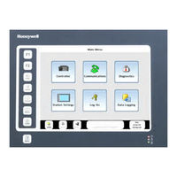
Figure 1 900 Control Station Menu
13
Typical Readers of this Guide
14
What You Can Do with the Control Station
14
Specifications
14
CE Conformity (Europe)
14
Components
15
Preparation and Startup
16
Site Preparation
16
Control Station Mounting
16
Noise Protection
16
How to Configure Your Control Station
16
Startup
17
Figure 2 Home Display
17
Features
19
Overview
19
Figure 3 Features
19
Touch Screen
20
Navigation and Data Entry
21
Figure 4 Examples of Buttons and Data Entry Fields
21
Status Bar
22
Figure 5 Status Bar
22
Keys
23
Compactflash
23
Status Leds
24
Figure 6 Status Leds
24
Ports
25
900 Control Station 10 Inch Model
25
900 Control Station 15 Inch Model
25
USB Device
26
USB Host
26
Ethernet
26
Rs485
26
Rs232
26
Main Menu
27
Overview
27
Access
27
Functions
27
Table 1 Main Menu Functions
27
Figure 7 Main Menu
27
Main Menu Tree
28
Table 2 Main Menu Tree
28
Controller
29
Controller Status
29
Table 3 Controller Status Details
29
Controller Setup
31
Table 4 Controller Setup Details
31
Table 5 Controller Modes Defined
31
Summary Displays
32
About Summary Displays
32
Communications
34
Menu Overview
34
Serial Port S1/S2
34
Table 6 Serial Port S1/S2 Statistics (Left Side of Display)
35
Table 7 Serial Port S1/S2: Port Diagnostic Status
36
Table 8 Serial Port S1/S2 Settings (Right Side of Display)
37
Table 9 Protocol Selection Versus Setup Parameters for the Serial Port S1/S2
38
Ethernet Port E1/E2 Status
39
Table 10 Ethernet Port E1/E2 Details
39
Table 11 Ethernet Port E1/E2: Port Diagnostic Status
40
Expansion Rack Communications
41
Table 12 Expansion Rack Communication Details
41
Table 13 Expansion Rack Communication Status
42
Modbus Slave Devices
43
Table 14 Modbus Slave Status
43
Host Connections
44
Table 15 Host Connections
44
Table 16 Host Connection Status Indicators
44
Peer Connections
45
Table 17 Peer Connections
45
Table 18 Peer Connection Status
46
Troubleshooting a Comm Quality Problem
47
Troubleshooting Data Link Errors
47
Diagnostics
48
Menu Overview
48
Controller Diagnostics
49
Table 19 Rack N Diagnostics
49
I/O Module Diagnostics and I/O Calibration
54
Table 20 I/O Module Diagnostics
54
Table 21 I/O Module Details
55
Table 22 I/O Module Error Status
56
Table 23 Bad Module Details
58
Table 24 Bad Channel Details
59
Communication Diagnostics
60
Redundant Overview
60
Table 25 Redundant Overview
60
Table 26 Details of Rack Diagnostics Error Status Messages
63
Lead/Reserve CPU Diagnostics
68
Table 27 Details of Lead or Reserve CPU Diagnostics Error Status Messages
69
Station Settings
73
View Data
73
Delete Data
73
Export Data to USB
73
Format Memory Device
74
Station Setup
74
Station Status
74
Station Comm Ports
74
Change Passwords
74
Language Menu Selection
74
Log on
75
Alarms and Events
76
Alarm Access
76
Alarm Definition
76
Alarm Indicator
76
Display Details
76
Alarm Groups
77
Alarm Group Indication
78
Alarm Group Overview
78
Alarm Point Indication
79
Alarm Point Detail
79
Alarm Acknowledgement
79
Event Access
80
Event Definition
80
Event Indication
80
Display Details
80
Data Logging
81
View Alarm & Event Logs
81
View Data Logs
82
View Audit Logs
82
Export Data Logs to USB
83
View Batch Groups & View Batch Status
83
Delete Data Logs
86
Downloading and Uploading Controller Configuration
87
Download Configuration Files
87
Upload Controller Configuration
89
Uploading Database Image
91
Uploading and Downloading Recipe Files
92
Download Recipe Files
92
Upload Recipe Files
94
Uploading and Downloading Security Settings
96
Upload Security Displays and Functionality
96
Download Security Displays and Functionality
98
Using Barcode Reader
98
Process Displays
99
Overview
99
Access
99
Widget Displays
99
How to Edit a Parameter
101
Pushbuttons, Signals and Variables
102
Aga8Dl & Aga8Gs
103
Table 28 AGA Parameters
104
Table 29 AGA Error Codes
104
AGA Detail Gas Components
107
AGA8 Gross Setup
108
4-Selector Switch
109
Device Control
110
Table 30 Device Control Display Details
110
Device Control Setup
111
Table 31 Device States
111
Hand/Off/Auto Switch
112
Stage
113
Stage Setup Display
114
Table 32 Stage Setup Details
114
Ramp
115
Table 33 Ramp Operator Display Details
115
Ramp Setup Display
116
Table 34 Edit Ramp Display Details
116
Alternator
117
Alternator Setup Display
118
Alternator Edit Setup Display
118
Calendar Event
121
Calendar Event Block Menu
122
Edit Event Setpoints
123
Set Active Setpoint Group
123
Edit Special Days
123
View Special Days Event Setup
124
Wireless Transmitters
125
XYR5000 Base Radio
125
XYR5000 Transmitter
126
XYR6000 Transmitter
127
Variable Recipes
129
Overview
129
Description
129
Variable Recipe Load Vs. Variable Recipe Upload/Download
129
Figure 8 Variable Recipe Selection Display
130
Setpoint Programmers
131
Overview
131
Description
131
Table 35 SPP Inputs and Current State
131
Setpoint Programmer Overview Widgets
132
Table 36 Setpoint Progammer Overview Widget Features
132
Setpoint Programmer - Pre Plot Display
134
General Description
134
Setpoint Programmer Pre-Plot Graph Attributes
135
Process Variable Trend Plot Attributes
136
Special Cases and Actions
136
Auxiliary SP and PV Pre-Plot
137
Setpoint Programmer Operate
137
Figure 9 Recipe Load
140
Figure 10 Recipe Save
140
View/Edit Profile
141
View/Edit Profile Segments
143
Edit Type and Value
143
Edit Events
144
Setpoint Scheduler
145
Overview
145
Table 37 SPS Inputs and Current State
145
Setpoint Scheduler Operate
146
Setpoint Schedulers
146
View/Edit Schedule
149
View/Edit Schedule Segments
150
Edit Setpoints
150
Edit Auxiliary Setpoints
150
Edit Time & Recycles
151
Edit Guarantee Hold
151
Edit Segment Events
151
Sequencers
153
Overview
153
Sequencer Operate
154
View/Edit Sequence
156
View/Edit Sequence Steps
157
Edit Time/Events
157
Edit Auxiliary
158
View Outputs 1-8/9-16
158
Loops
159
Overview
159
Loop Widgets
159
Loops (A/M Bias, Carbon, On/Off, PID, 3 Position Step Control)
159
Loop Setup
160
Overview
160
Loop Modes
161
Table 38 Loop Modes
161
Figure 11 IMAN Loop Mode
161
Loop Control Setup
162
Loop Tuning
163
Tuning Constants
167
Alarm Setpoints
168
High Output Limiting
169
I/O Calibration
171
Menu Overview
171
Overview
172
AI Calibration
173
Overview
173
Calibration Equipment
173
Calibrate AI Channel
174
Cancel Calibration
174
Restore AI Factory Calibration
174
CJ Calibration
175
Cancel Calibration
175
Restore CJ Factory Calibration
175
AO Calibration
176
Cancel Calibration
177
Restore AO Factory Calibration
177
PPO Motor Calibration
178
Overview
178
Calibration Status Information
178
Cancel Calibration
179
Calibration Errors
179
Table 39 Calibration Errors
179
Auto Calibration Procedure
180
Table 40 Auto Calibration Procedure
180
Semi-Auto Calibration Procedure
181
Table 41 Semi-Auto Calibration Procedure
181
Hand Calibration Procedure
182
Table 42 Hand Calibration Procedure
182
Motor Setup
184
Maintenance
185
Troubleshooting
185
What to Do if the Control Station Has Difficulty Starting up
185
Performing a Cold Start
185
What to Do if You Want to Change the IP Address at the Control Station
186
Changing or Entering IP Address
186
How to Remove the Rear Cover and Change the Battery of the Operator Interface
187
Changing the Battery of Control Station Unit
187
Parts
188
Table 43 Parts
188
Index
189
Sales and Service
192
Advertisement
Related Products
Honeywell 9410 Series
Honeywell 9000 color touchscreen
Honeywell INTELLIGUARD 9000
Honeywell 9007AX01
Honeywell 900CS10-00
Honeywell 900CS15-00
Honeywell ControlEdge 900R04-0200
Honeywell ControlEdge 900RR0-0200
Honeywell ControlEdge 900R12R-0200
Honeywell ControlEdge 900R08R-0200
Honeywell Categories
Thermostat
Controller
Control Unit
Security Camera
Accessories
More Honeywell Manuals
Login
Sign In
OR
Sign in with Facebook
Sign in with Google
Upload manual
Upload from disk
Upload from URL