Sign In
Upload
Manuals
Brands
Canon Manuals
All in One Printer
iR5075N
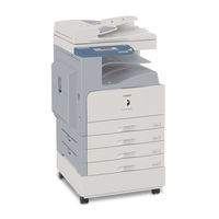
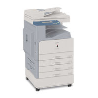
User Manuals: Canon iR5075N Mono Laser Printer
Manuals and User Guides for Canon iR5075N Mono Laser Printer. We have
3
Canon iR5075N Mono Laser Printer manuals available for free PDF download: Service Manual, User Manual, Easy Operation Manual
Canon iR5075N Service Manual (646 pages)
Brand:
Canon
| Category:
Copier
| Size: 22.01 MB
Table of Contents
Table of Contents
7
Table of Contents
18
Chapter 1 Introduction
29
Table of Contents
31
System Construction
33
System Configuration with Pickup/Delivery Accessories (230V)EUR
33
System Configuration with Printing/Transmission Accessories (230V)EUR
33
Functions and Printing/Transmission Accessories (230V)
34
Product Specifications
35
Names of Parts
35
External View
35
Cross-Section
37
Using the Machine
39
Turning on the Power Switch
39
Turning off the Power Switch
39
Control Panel
41
User Mode Items
41
Common Settings
41
Timer Settings
43
Adjustment/Cleaning
43
Report Output
43
Cleaning
43
System Control Settings
44
Copier Specifications
46
Transmission/Reception Settings
47
Box Settings
48
Printer Settings
48
Address Book Settings
50
Voice Guide Settings
51
Maintenance by the User
51
Cleaning
51
Checks
52
Safety
53
Safety of the Machine's Laser Unit
53
CDRH Regulations
53
Handling the Machine's Laser Unit
54
Safety of Toner
54
Product Specifications
54
Function List
56
Printing Speed
56
Paper Types/Printing Speed (K Paper)
56
Paper Types/Printing Speed (K Paper)
57
Table of Contents
61
Chapter 2 Selecting the Installation Space
63
Combination Table of Accessories
64
Checking the Contents
65
Making Pre-Checks
63
Unpacking and Installation
67
Unpacking and Installation Procedure
67
Unpacking
67
Installation of Scanner
69
Installation of Fixing Assembly
69
Checking of Charging Assembly and Dustproof Glass
70
Installation of Developing Assembly
71
Installation of Pickup Assembly
72
Attaching Deck Pressure Plate
73
Setting Toner Container
73
Connecting the Cable
74
Checking the Environment Switch
74
Attaching the Label
75
Connecting the Power Cord
75
Turning on the Main Power Switch
76
Toner Stirring
76
Media Cassette Settings
76
Index Paper Attachment
76
Changing the Media Size of the Front Deck (Left/Right)
77
Image/Operation Check in User Mode
77
Adjustment of Image Left End Margin
77
Adjustment of Image Leading Edge Margin
78
Mounting of the Host Machine
78
Checking the Connection to the Network
81
Overview
81
Using the Ping Command
81
Making a Check Using the Remote Host Address
81
Troubleshooting the Network
81
Checking the Connection of the Network Cable
81
Making a Check Using a Loopback Address
81
Making a Check Using a Local Host Address
81
Relocating the Machine
82
Operation for Moving the Machine
82
Installing the Copy Tray
82
Confirming the Contents
82
Power off of the Host Machine
82
Installation Procedure
82
Installing the Card Reader
84
Notice at Installation
84
Confirming the Contents
84
Power off of the Host Machine
84
Installation Procedure
84
Installing for Imageware Accounting Manager
86
Installing the Original Holder
86
Checking Contents
86
Installation Procedure
86
Checking Contents
87
Installation Procedure
87
Installing the Reader Heater
87
Checking the Contents
87
Power off of the Host Machine
87
Installation Procedure
88
Installing the Cassette Heater
89
Checking Components
89
Power off of the Host Machine
90
Installation Procedure of the Cassette Heater
90
Installing the Deck Heater
92
Checking the Parts to Install
92
Turning off the Host Machine
93
Installing the Deck Heater (Large Deck)
93
Checking the Parts to Install
93
Turning off the Host Machine
94
Installing the Voice Guidance Kit
94
A Point to Keep in Mind at Installation
94
Checking the Contents
94
Power off of the Host Machine
95
Installation Procedure
95
Installing the Wireless Network Interface Adapter
101
Points to Note When Installing
101
Checking the Contents
101
Power off of the Host Machine
101
Installation Procedure
101
Affixing the Label
103
Construction/Basic Sequence
107
Construction
109
Functional Construction
109
Wiring Diagram of the Major Pcbs
109
Controlling the Main Motor (M2)
110
Basic Sequence
111
Basic Sequence of Operation (at Power-On; 30-Sec Start-Up Mode)
111
Basic Sequence of Operation (at Power-On; Low-Temperature Start-Up Mode)
111
Basic Sequence of Operation (at Power-On; High-Humidity Start-Up Mode)
112
Basic Sequence of Operation (at Time of Copying/Printing)
113
Table of Contents
117
Construction
119
Construction and Mechanisms
119
Construction of the Electrical Circuitry
119
Main Controller PCB
119
Hdd
121
Chapter 11 MEAP
122
Start-Up Sequence
122
Overview
122
Image Processing
124
Overview of the Image Flow
124
Construction of the Image Processing Module
125
Reader Unit Input Image Processing
125
Compression/ Extension/ Editing Block
126
Printer Unit Output Image Processing
126
Shut-Down Sequence
124
Overview
124
Flow of Operation
124
Flow of Image Data
127
Flow of Image Data According to Copy Functions
127
Flow of Image Data for the Box Function
127
Flow of Image Data for the SEND Function
128
Flow of Image Data for the Fax Transmission
128
Flow of Image Data for the Fax Reception Function
129
Flow of Image Data for the PDL Function
130
Parts Replacement Procedure
131
Main Controller Box
131
Before Removing the Main Controller Box
131
Removing the Main Controller Box
131
Main Controller PCB
131
Before Removing the Main Controller PCB
131
Removing the Main Controller PCB
131
When Replacing the Main Controller PCB
132
Sdram
132
Before Removing the SDRAM
132
Removing the SDRAM
132
Boot ROM
132
Before Removing the Boot ROM
132
Removing the Boot ROM
132
Hdd
133
Before Removing HDD
133
Removing the HDD
133
After Replacing the HDD
133
Video PCB
133
Before Removing the Video PCB
133
Removing the Video PCB
133
Controller Fan
134
Before Removing the Controller Cooling Fan
134
Removing the Controller Cooling Fan
134
Table of Contents
137
Construction
139
Specifications, Controls, and Functions
139
Major Components
139
Construction of the Control System
140
Reader Controller PCB
141
Basic Sequence
142
Basic Sequence of Operations
142
Basic Sequence of Operation in Response to a Press on the Start Key
143
Various Control
143
Controlling the Scanner Drive System
143
Overview
143
Controlling the Scanner Motor
144
Enlargement/Reduction
145
Changing the Magnification in Main Scanning Direction
145
Changing the Magnification in Sub Scanning Direction
145
Controlling the Scanning Lamp
146
Overview
146
Scanning Lamp
146
Controlling the Activation
146
Detecting the Size of Originals
147
Overview
147
Controlling the Activation
147
Overview of Operation
148
Dirt Sensor Control
150
Dust Detection in Stream Reading Mode
150
White Plate Dust Detection Control
151
Image Processing
152
Overview
152
CCD Drive
153
CCD Output Gain Correction, Offset Correction
153
CCD Output A/D Conversion
153
Outline of Shading Correction
153
Shading Adjustment
154
Shading Correction
154
Parts Replacement Procedure
155
CCD Unit
155
Before Removing the CCD Unit
155
Removing the CCD Unit
155
When Replacing the CCD Unit
155
Copyboard Glass
156
Removing the Copyboard Glass
156
When Replacing the Copyboard Glass
156
Scanning Lamp
156
Before Removing the Scanning Lamp
156
Removing the Scanning Lamp
156
When Replacing the Scanning Lamp
157
Reader Controller PCB
157
Before Removing the Reader Controller PCB
157
Removing the Reader Controller PCB
157
After Replacing the Reader Controller PCB
158
Interface PCB
158
Before Removing the Interface PCB
158
Removing the Interface PCB
158
Before Removing the Memory PCB
159
Removing the Memory PCB
159
Before Removing the Inverter PCB
159
Removing the Inverter PCB
159
After Replacing the Inverter PCB
160
Scanner Motor
160
Before Removing the Scanner Motor
160
Removing the Scanner Motor
160
Mounting the Scanner Motor
161
ADF Open/Close Sensor
161
Before Removing the ADF Open/Close Sensor
161
Removing the ADF Open/Close Sensor
161
Scanner HP Sensor
161
Before Removing the Scanner HP Sensor
161
Removing the Mirror Base HP Sensor
161
Original Size Sensor
162
Before Removing the Original Size Sensor
162
Removing the Original Size Sensor
162
Cooling Fan
163
Before Removing the Cooling Fan
163
Removing the Cooling Fan
163
Scanner Drive Cable
163
Outline
163
Before Removing the Scanner Drive Cable
163
Removing the Scanner Drive Cable
163
Fitting the Scanner Drive Cable
166
Adjusting the Position of the No. 1/No. 2 Mirror Base
166
Waste Toner Box Holder
167
Before Removing the Collecting Toner Bottle Holder
167
Removing the Collecting Toner Bottle Holder
167
Construction/Parts Replacement Procedure
171
Construction
173
Overview
173
Major Components
173
Various Controls
174
APC Control
175
Controlling the Laser Scanner Motor
176
Parts Replacement Procedure
177
Laser Scanner Unit
177
Removing the Laser Scanner Unit
177
When Replacing the Laser Scanner Unit
177
Table of Contents
181
Construction
185
Overview
185
Major Components
185
Image Formation Process
185
Basic Sequence
186
At Power-On
186
At Time of Printing
187
Potential Control
187
Overview
187
Copier/Printer Potential Control
187
Determining the Primary Current
190
Determining the Laser Output
190
Determining the Developing Bias
190
APC Correction
191
Adjusting the Density in Various Modes
191
Charging Mechanism
192
Controlling Pre-Exposure LED
192
Pre-Exposure LED Control
192
Primary Charging Mechanism
193
Overview
193
Primary Charging Assembly Cleaning Mechanism
193
Others
194
Dust-Collecting Roller Bias
194
Overview
194
Chapter 7 Image Formation
195
Pre-Transfer Charging Mechanism
195
Pre-Transfer Charging Assembly Cleaning Mechanism
196
Others
196
Drum Cleaner Unit
196
Overview
196
Detecting the State (Full) of the Collecting Toner Case
197
Drum/Separation Claw Bias Control
198
Developing Assembly
198
Controlling the Developing Assembly Drive
198
Controlling the Developing Bias
198
Detecting the Toner Level and Controlling Toner Supply
199
Transfer Mechanism
200
Transfer Charging Mechanism
200
Overview
200
Controlling the Output to Suit the Environment (Fuzzy Control)
200
Transfer Charging Assembly Cleaning Mechanism
201
Others
201
Separation Mechanism
202
Separation Charging Mechanism
202
Overview
202
Correcting the Output to Suit the Environment and the Drum Surface Potential
202
Others
203
Parts Replacement Procedure
204
Process Unit
204
Before Removing Process Unit
204
Removing Process Unit
204
Mounting Process Unit
204
Pre-Exposure Lamp
205
Before Removing Pre-Exposure Lamp
205
Removing Pre-Exposure Lamp
205
Cleaning Primary Toner Blocking Sheet
205
Primary Charging Assembly
205
Before Removing Primary Charging Assembly
205
Removing Primary Charging Assembly
205
Photosensitive Drum
206
Points to Note When Handling Photosensitive Drum
206
Before Removing Photosensitive Drum
206
Removing Photosensitive Drum
206
Cleaning Photosensitive Drum
207
Pre-Transfer Charging Assembly
206
Before Removing Pre-Transfer Charging Assembly
206
Removing Pre-Transfer Charging Assembly
206
Drum Motor
207
Before Removing Drum Motor
207
Removing Drum Motor
207
Cleaning Blade
208
Configuration
208
Before Removing Cleaning Blade
208
Removing Cleaning Blade
208
Mounting Cleaning Blade
209
Photosensitive Drum Heater
208
Points to Note When Handling Photosensitive Drum
208
Before Removing Photosensitive Drum Heater
208
Removing Drum Heater
208
Points to Note When Mounting Drum Heater
208
Side Seal
209
Before Removing Side Seal
209
Removing Side Seal
210
Cleaner Scraper
210
Before Cleaning Cleaner Scraper
210
Cleaning Cleaner Scraper
210
Hopper Assembly
210
Before Removing Hopper Assembly
210
Removing Hopper Assembly
210
Hopper Strring Motor
211
Before Removing Hopper Stirring Motor
211
Removing Hopper Stirring Motor
211
Hopper Supply Motor
211
Before Removing Toner Supply Motor
211
Removing Toner Supply Motor
211
Developing Assembly
212
Removing Developing Assembly
212
Cleaning Developing Toner Blocking Sheet
212
Developing Blade
213
Before Removing Developing Blade
213
Removing Developing Blade
213
Mounting Developing Blade
213
Developing Cylinder
213
Before Removing Developing Cylinder
213
Removing Developing Cylinder
213
Separation Claw/Separation Claw Drive Assembly
214
Transfer/Separation Charging Assembly
214
Removing Transfer/Separation Charging Assembly
214
Mounting Transfer/Separation Charging Assembly
214
Potential Sensor Unit
215
Routing Grid for Primary Charging Assembly
216
Table of Contents
219
Construction
223
Specifications and Construction
223
Arrangement of Rollers and Sensors
223
Outline of the Pickup Control System
225
Chapter 8 Pickup/Feeding System
227
Outline of the Pickup Assembly Motor Control System
227
Basic Sequence
228
Pickup from the Right Deck
228
Pickup from the Cassette 3
229
Pickup Retry Operation
230
Detecting Jams
230
Jam Detection Outline
230
Outline
230
Jam History
232
Delay Jams
232
Cassette Pickup Assembly (Right Deck, Left Deck, Cassette 3/4)
232
Other Delay Jam
232
Stationary Jams
233
Common Delay Jams
233
Power-On Stationary Jam
234
Cassette Pick-Up Unit
234
Lifter Operation (Cassette 3/4)
234
Detecting the Presence/Absence of Paper
235
Outline of the Paper Level Detection Mechanism
236
Paper Level Detection (Cassette 3/4)
236
Identifying the Size of Paper (Cassette 3/4)
236
Markings on the Width Guide Rail
237
Paper Size
237
Manual Feed Pickup Unit
239
Pickup Operation
239
Detecting the Size of Paper in the Manual Feed Tray
240
Deck
241
Lifter Operation (Right/Left Deck)
241
Lifter Limiter (Right/Left Deck) Control Circuit
241
Detecting the Presence/Absence of Paper
242
Paper Level Detection Operation (Right/Left Deck)
243
Identifying the Size of Paper (Right/Left Deck)
243
Registration Unit
243
Outline
243
Control System
244
Duplex Feeding Unit
244
Moving the Paper to the Reversing Assembly after Printing on the 1St Side
244
Moving the Paper to the Duplexing Feed Assembly from the Reversing Assembly
244
Outline
245
Outline of Through-Path Operation
246
Through-Path Operation
246
Outline of Horizontal Registration Position
250
Horizontal Registration Position Detection Operation
250
Delivery
251
Reversal Delivery Operation
251
Cassette Heater
252
Timing of the Cassette Heater Supplied with Power
252
Parts Replacement Procedure
253
Pickup Roller
253
Before Removing the Pickup Roller
253
Removing the Pickup Roller
253
Points to Note When Mounting the Pickup Roller
253
Cassette Pickup Assembly
253
Removing the Cassette 3/4 Pickup Assembly
253
Cassette Pickup Motor
253
Before Removing the Cassette 3/4 Pickup Motor
253
Removing the Cassette 3/4 Pickup Motor
253
Cassette Lifter Motor
254
Removing the Cassette 3 Lifter Motor M20
254
Removing the Cassette 4 Lifter Motor M21
254
Adjusting the Position of the Lifter Motor M20/M21 of the Cassette 3/4
255
Left Deck Lifter Motor
255
Before Removing the Left Deck Lifter Motor
255
Removing the Left Deck Lifter Motor
255
Right Deck Lifter Motor
256
Before Removing the Right Deck Lifter Motor
256
Removing the Right Deck Lifter Motor
256
Right Deck Pickup Assembly
257
Before Removing the Left Deck Pickup Motor
258
Removing the Left Deck Pickup Motor
258
Right Deck Pickup Motor
258
Before Removing the Right Deck Pickup Motor
258
Removing the Right Deck Pickup Motor
258
Left Deck Pickup Sensor
258
Before Removing the Left Deck Feeding Sensor
258
Removing the Left Deck Feeding Sensor
258
Left Deck Pickup Solenoid
258
Before Removing the Left Deck Pickup Solenoid
258
Removing the Left Deck Pickup Solenoid
259
Adjusting the Position of the Left Deck Pickup Solenoid
259
Manual Feed Pull-Out Roller Unit
259
Removing the Manual Feeding Pickup Roller Unit
259
Manual Feed Pull-Out Roller
259
Before Removing the Manual Feeding Pickup Roller
259
Removing the Manual Feeding Pickup Roller
259
Manual Feed Roller
260
Before Removing the Manual Feeding Roller
260
Removing the Manual Feeding Roller
260
Manual Separation Roller
260
Before Removing the Manual Separation Roller
260
Removing the Manual Separation Roller
260
Adjusting the Pressure of the Manual Separation Roller
260
Manual Feed Tray Paper Sensor
261
Removing the Manual Feeding Tray Sensor
261
Registration Roller
261
Before Removing the Registration Roller
261
Removing the Registration Roller
261
Pre-Registration Roller
262
Before Removing the Registration Lower Roller
262
Removing the Registration Lower Roller
262
Before Removing the Horizontal Registration Motor
263
Pre-Registration Motor
263
Registration Sensor
264
Before Removing the Horizontal Registration Sensor
264
Removing the Horizontal Registration Sensor
264
Registration Clutch
265
Before Removing the Registration Clutch
265
Removing the Registration Clutch
265
Registration Brake Clutch
265
Before Removing the Registration Brake
265
Removing the Registration Brake
265
Feeding Roller
265
Before Removing the Feeding Roller
265
Removing the Feeding Roller
265
The Points to Mount the Feeding Roller
266
Vertical Path Roller
266
Before Removing the Vertical Path Roller
266
Removing the Vertical Path Roller
266
Removing the Vertical Path Roller 2/3
266
Vertical Path Motor
266
Before Removing the Vertical Path Upper Motor
266
Removing the Vertical Path Upper Motor
267
Vertical Path Duplex Motor
267
Before Removing the Vertical Path Duplex Motor
267
Removing the Vertical Path Duplex Motor
267
Vertical Path Lower Motor
267
Before Removing the Vertical Path Lower Motor
267
Removing the Vertical Path Lower Motor
267
Reversing Motor
267
Before Removing the Reversing Motor
267
Before Removing the Fixing Feeding Unit Release Lever Sensor
268
Removing the Fixing Feeding Unit Release Lever Sensor
268
Removing the Reversing Motor
268
Before Removing the Reversing Flapper Solenoid
269
Feeding Belt
270
Before Removing the Feeding Belt
270
Removing the Feeding Belt
270
Duplexing Unit
271
Before Removing the Duplex Feeding Unit
271
Removing the Duplex Feeding Unit
271
Duplex Feed Motor
271
Before Removing the Duplex Feeding Left Motor
271
Removing the Duplex Feeding Left Motor
271
Before Removing the Duplex Feeding Right Motor
271
Removing the Duplex Feeding Right Motor
271
Duplex Feed Sensor
271
Before Removing the Duplex Pre-Registration Sensor
271
Separation Roller
272
Before Removing the Separation Roller
272
Removing the Separation Roller
272
Points to Note When Mounting the Separation Roller
272
Adjusting the Pressure of the Deck/Cassette Separation Roller
273
Table of Contents
277
Construction
281
Specifications, Control Mechanisms, and Functions
281
Major Components
281
IH Fixing Method (Outline)
283
Limiting Th Rise in Temperature at the Roller Edges by Use of a Flux Blocking Plate (Shutter)
283
Basic Sequence
284
Outline
284
30-Sec Start-Up Mode
284
Low-Temperature Environment Start-Up Mode
285
High-Humidity Environment Start-Up Mode
285
Recovery Mode
286
Standby Mode
286
Power Save Mode
287
Sleep Mode
287
Copying/Printing Mode
287
Down Sequence
288
Enhanced Fixing Mode
288
Heavy Paper Mode
289
Transparency Mode
289
Bond Paper Mode
289
Chapter 9 Fixing System
290
Various Control Mechanisms
290
Controlling the Reciprocating Movement of the Thermistor
291
Controlling the Reciprocating Mechanism of the Upper Separation Claw
291
Controlling the Drive of the Shutter
292
Controlling the Shutter Position
293
Cleaning
294
Controlling the Drive of the Cleaning Web
294
Controlling the Mechanism Used to Detect the Remaining Length of the Cleaning Web
295
Detecting the Passage of Paper
296
Preventing Wrapping of Paper
296
Protective Functions
297
Detecting an Error Using the Thermistor
297
Detecting an Error Using the Thermal Switch
297
Parts Replacement Procedure
299
Fixing/Feeding Assembly
299
Before Removing the Fixing/Feeding Unit
299
Removing the Fixing/Feeding Unit
299
Fixing Unit
300
Upper Fixing Roller
301
Before Removing the Fixing Roller
301
Removing the Fixing Roller
301
Points to Note When Mounting the Fixing Roller
303
Applying Grease after Replacing the Fixing Roller
304
Adjusting the Nip Width
305
External Delivery Roller
305
Before Removing the External Delivery Roller
305
Removing the External Delivery Roller
305
Internal Delivery Roller
306
Before Removing the Internal Delivery Roller
306
Removing the Internal Delivery Roller
306
Points to Note When Mounting the Internal Delivery Roller
307
Points to Note When Mounting the Main Thermistor/Shutter Thermistor
308
Sub Thermistor
308
Before Removing the Sub Thermistor
308
Removing the Sub Thermistor
309
Removing the Thermal Switch
310
Fixing Cleaning Belt
312
Before Removing the Fixing Web
312
Removing the Fixing Web
312
Cleaning the Fixing Oil Dish and the Fixing Cleaning Belt Guide
312
Mounting the Fixing Web
312
After Replacing the Fixing Web
313
Claw Jam Sensor
313
Before Removing the Claw Jam Sensor
313
Removing the Claw Jam Sensor
313
Fixing Jam Sensor
313
Before Removing the Delivery Jam Sensor
313
Removing the Delivery Jam Sensor
313
External Delivery Sensor
314
Before Removing the External Delivery Sensor
314
Removing the External Delivery Sensor
314
Fixing Inlet Sensor
314
Before Removing the Fixing Inlet Sensor
314
Removing the Fixing Inlet Sensor
314
Adjusting the Fixing Inlet Guide
315
Internal Delivery Sensor
314
Before Removing the Internal Delivery Sensor
314
Removing the Internal Delivery Sensor
314
Fixing Shutter Motor
315
Before Removing the Shutter Motor
315
Removing the Shutter Motor
315
Fixing Shutter Sensor
315
Before Removing the Shutter Sensor
315
Removing the Shutter Sensor
315
Fixing Web Sensor
315
Before Removing the Fixing Web Sensor
315
Removing the Fixing Web Sensor
315
Delivery Flapper Solenoid
316
Before Removing the Delivery Flapper Solenoid (SL5)
316
Removing the Delivery Flapper Solenoid (SL5)
316
Fixing Inlet Guide Solenoid
316
Before Removing the Fixing Inlet Guide Solenoid (SL1)
316
Removing the Fixing Inlet Guide Solenoid (SL1)
316
Adjusting the Fixing Inlet Guide Solenoid (SL1)
316
Points to Note When Mounting the Delivery Flapper Solenoid (SL5)
317
Points to Note When Mounting the Upper Separation Claw
318
Removing the Lower Separation Claw (Unit)
319
Advertisement
Canon iR5075N User Manual (98 pages)
Brand:
Canon
| Category:
All in One Printer
| Size: 5.2 MB
Table of Contents
Manuals for the Machine
4
Table of Contents
6
Preface
8
How to Use this Manual
8
Symbols Used in this Manual
8
Legal Notices
9
Product Name
9
EMC Directive
9
Laser Safety
10
Additional Information
10
International Energy Star Program
11
WEEE Directive
11
R&TTE Directive
12
Super G3
12
Abbreviations Used in this Manual
12
Trademarks
13
Copyright
13
Disclaimers
18
Legal Limitations on the Usage of Your Product and the Use of Images
19
Important Safety Instructions
20
Installation
20
Power Supply
21
Handling
22
Maintenance and Inspections
25
Loading Paper
25
Replacing the Toner Cartridge
25
Consumables
26
Other Warnings
26
About the Electronic Instruction Manuals
27
Contents of Documentation Kits
27
Multi-Lingual Documentation Kit
27
Documentation Kit Included in Box
27
Documentation Only in Send Kit
27
User Manual Disc Menu
28
System Requirements
28
Using the Disc Menu
29
Periodic Inspection of the Breaker
30
Checking the Breaker
30
Chapter 1 Before You Start Using this Machine
34
Installation Location and Handling
34
Installation Precautions
34
Avoid Installing the Machine in the Following Locations
34
Select a Safe Power Supply
37
Provide Adequate Installation Space
38
Moving the Machine
39
Handling Precautions
39
What this Machine Can Do
42
System Configuration and Parts
45
Optional Equipment
45
External View and Internal View
47
Control Panel Parts and Functions
49
Touch Panel Display
50
Main Power and Control Panel Power
53
How to Turn on the Main Power
53
Things You Must Do before Using this Machine
57
Selecting the Type of Telephone Line
57
Setting the Current Date and Time
58
Registering Your Machine's Fax Number
59
Registering Sender Names
60
Registering the Unit's Name
61
Displaying a Help Screen
63
Canon iR5075N Easy Operation Manual (60 pages)
Brand:
Canon
| Category:
All in One Printer
| Size: 21.62 MB
Table of Contents
Table of Contents
1
Basic Features
1
How the Manuals Are Divided
2
What You Can Do with this Machine
4
The Control Panel
6
Copying Function
8
Making a Copy
8
What You Can Do with this Machine (Regular Copy Basic Features Screen)
10
To Enlarge/Reduce an Image to Copy to a Different Size Paper
10
To Staple Sets of Output Together
10
To Interrupt a Long Copy Job to Make Priority Copies
11
To Copy Onto Irregular Sized Paper
11
To Make Two-Sided Copies
11
What You Can Do with this Machine (Special Features Screen)
12
To Copy Different Size Originals Together
12
To Copy Facing Pages in a Book
12
To Copy Multiple Originals Onto One Sheet of Paper
13
To Make a Booklet
13
To Erase the Dark Border When Copying a Book
14
To Add a Margin
14
To Add a Cover
15
To Recall Commonly Used Settings
15
To Scan Batches of Originals
16
To Add Page Numbers to Copies
17
To Add a Watermark to Copies
17
To Store Scanned Originals with Copy Settings
18
To Embed Hidden Text in the Background
18
To Combine Multiple Batches of Originals with Different Copy Settings
19
Overview of Copy Features
20
Facsimile Function
22
Sending a Fax
22
What You Can Do with this Machine (Fax Screen)
24
If You Mainly Use One-Touch Buttons
24
To Display the Sender History
24
To Automatically Forward Received Faxes
25
To Send Data from a Computer by Fax
25
Sending Function
26
Sending a Document
26
Ser Ver)
27
What You Can Do with this Machine (Address Book/Send Basic Features Screen)
28
To Register Commonly Used Destinations
28
To Recall the Last Settings
28
To Specify a File Format and Send a Document
29
What You Can Do with this Machine (Scan Settings Screen)
30
To Send Documents Containing Photos Clearly
30
To Change the Scanned Document Size
30
To Automatically Change the Zoom Ratio According to a Specifi Ed Record Size
31
To Send Fine Text and Images Clearly
31
To Send Separately Scanned Documents at Once
31
What You Can Do with this Machine (Send Settings Screen)
32
To Add the Reply Destination to a Sent Document
32
To Specify the Time to Start Sending
33
To Send Notifi Cation of Completed Sending
33
To Confi Rm a Document before Sending
33
To Edit a Destination from a Computer
33
Sending/Facsimile Function
34
Overview of Sending/Fax Features
34
Mail Box Function
38
Storing Originals in an Inbox
38
Printing/Sending a Document Stored in a User Inbox
40
What You Can Do with this Machine (Scan Screen)
42
To Add a Name to a Document and Save It
42
To Scan a Two-Sided Document
42
To Confi Rm/Erase Documents in a User Inbox from Your Computer
43
What You Can Do with this Machine (Change Print Settings Screen)
44
To Print a Sample Print
44
To Automatically Delete Document Data after Printing
45
To Print Multiple Documents Together
45
To Output Print Documents in Sets
45
To View Documents Stored in a User Inbox
45
Mail Box Function Overview
46
Advertisement
Advertisement
Related Products
Canon IR5000 - iR B/W Laser
Canon iR5065N
Canon iR5075
Canon iR5055
Canon iR5055N
Canon iR5065
Canon iR5570 Series
Canon iR5020i
Canon iR5020N
Canon iR5570N
Canon Categories
Printer
Digital Camera
All in One Printer
Camcorder
Scanner
More Canon Manuals
Login
Sign In
OR
Sign in with Facebook
Sign in with Google
Upload manual
Upload from disk
Upload from URL