Sign In
Upload
Manuals
Brands
Abaco Systems Manuals
Motherboard
CT9 Series
Abaco Systems CT9 Series Manuals
Manuals and User Guides for Abaco Systems CT9 Series. We have
1
Abaco Systems CT9 Series manual available for free PDF download: Hardware Reference Manual
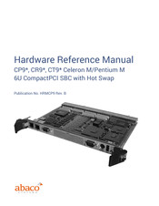
Abaco Systems CT9 Series Hardware Reference Manual (91 pages)
Celeron M/Pentium M 6U CompactPCI SBC with Hot Swap
Brand:
Abaco Systems
| Category:
Motherboard
| Size: 2.12 MB
Table of Contents
Document History
2
About this Manual
3
Further Information
4
Table of Contents
7
1 Introduction
13
Board Design
14
Figure 1-1 Block Diagram of CR9 Board
14
Features
15
Table 1-1 Styles Available
17
Safety Notices
18
EMI/EMC Regulatory Compliance
18
ESD/EMI Issues
18
CE Conformance Declaration
19
2 Unpacking and Inspection
20
Delivery Volume
20
Available Accessories
20
Table 2-1 Delivery Volume
20
Table 2-2 List of Accessory Options
20
Esd
21
Warning
21
Initial Inspection
21
Unpacking
22
Handling
23
Figure 2-1 Board Packaging
23
Figure 2-2 Handling the CR9 Board
24
3 Installation
25
Installation Preparation
25
General Advisories
25
Advice on Compactpci Products
25
Required Items
26
Backplane and Power Supply
26
Keyboard and Mouse
26
Video Monitor
27
Advice on Batteries
27
Installation of a Plug-In Board
27
Installation of a Plug-On Module (Mezzanine)
27
Figure 3-1 6U Board Insertion into System Box
27
Installation of the Rear Transition Module CTM12
28
Figure 3-2 Installing a PMC on a 6U CPCI Carrier Board
28
Initial Power-On Operation
29
Entering the BIOS SETUP
29
Table 3-1 BIOS ID Line
29
4 Getting Started
30
Power Supply
30
Status Indicator, Postcode and Beeps
30
Booting
31
Setup
32
Hot Swap on CR9
32
Table 4-1 Boot Timing
32
Unexpected Results
33
5 Interfaces
34
Front Panel Interfaces
34
Figure 5-1 Location of Components on Board and Front Panel
34
Figure 5-2 Single Slot Front Panel
34
CR9 Connectors
35
CPCI Connector Reference
35
Figure 5-3 Dual Slot Front Panel
35
Table 5-1 Signal Name Groups
35
Compactpci Bus Connector J7001 and J7002
36
Table 5-2 CPCI Connectors J7001, J7002
36
I/O Connector J7003, J7004, and J7005
37
Table 5-3 I/O Connectors J7003, J7004, and J7005
37
EIDE Connector P1800
39
Figure 5-4 EIDE Connector Location
39
Keyboard and PS/2 Mouse Interface P2001
40
Figure 5-5 Keyboard and Mouse Connector Location
40
Table 5-4 EIDE Connector
40
Ethernet Interface U5600 and U5650
41
Figure 5-6 Keyboard and Mouse Connector Layout
41
Figure 5-7 Ethernet Connector Location
41
Figure 5-8 Ethernet Connector Layout
41
Table 5-5 Keyboard and Mouse Pin Assignments
41
Serial Port COM1 P2201
42
Figure 5-9 COM1 Location
42
Table 5-6 Ethernet Connector Pin Assignments
42
Table 5-7 Ethernet LED Display Definitions
42
VGA Interface P4200
43
Figure 5-10 VGA Connector Location
43
Table 5-8 COM1 Pin Assignments
43
Table 5-9 VGA Connector Pin Assignments
43
USB Interfaces P1680
44
PMC1 Connectors P6201, P6202, and P6203
44
Figure 5-11 USB Connector Location
44
Figure 5-12 USB Connector Layout
44
Table 5-10 USB Connector Pin Assignments
44
Table 5-11 PMC1 Connector Pin Assignments
45
PMC2 Connectors P7201, P7202
46
Table 5-12 PMC2 Connector Pin Assignments
47
PMC I/O Connector P6204 and P7204
48
Transition Module
48
6 Resources
49
Memory Map
49
Register Set
49
Table 6-1 Memory Area Assignments
49
Plug and Play Devices
50
Standard Register Set
50
Table 6-2 Standard Register Set
50
Interrupts
51
Table 6-3 Interrupt Assignments
51
APIC Controller
52
7 Function Blocks
53
Processor
53
Memory Controller
53
DMA Controller
53
Interrupt Controller
53
Timer
54
Real Time Clock
54
Table 7-1 Interval Timer Functions
54
Keyboard and Mouse Controller
55
EIDE Interface
55
USB Interface
55
Serial Interface
55
Parallel Interface
56
Floppy Controller
56
Graphics Controller
56
Table 7-2 Parallel Interface Options
56
Software Installation
57
PMC Interface
57
Ipmi (Ct9)
57
Ipmb
58
Private I C
58
Software Installation
58
Ethernet Interface
58
Table 7-3 IPMB Backplane Pin Assignments
58
Table 7-4 Supported Operating Systems
58
Additional Devices
59
Hot Swap
59
Smbus Devices
60
Smbus External (IPMB)
60
Temperature Sensor LM83
60
Table 7-5 Smbus Devices
60
Temperature Sensors LM75
61
Serial EEPROM
61
Power Management Event
61
Intp, Ints
61
Enum
61
Table 7-6 Power Management Events
61
Geographic Addressing
62
Gpio (0
62
Watchdog
62
Programmable Timer
62
Leds
62
Reset Button
63
Speaker
63
Table 7-7 BIOS Power-Up Status
63
8 Specifications
64
Pcb
64
Size
64
Dimensions
64
Mechanical Incompatibility
64
Weight
64
Rohs Compliance
64
Power Consumption
64
Table 8-1 Power Consumption CPU Dependent
65
Table 8-2 Power Consumption DRAM Dependent
65
Onboard Lithium Battery
66
Not Powered by the System
66
Figure 8-1 Battery Current Versus Temperature
66
Powered by the System
67
Figure 8-2 Battery Current Versus Time
67
Battery Removal and Replacement
68
External Battery Input
68
Figure 8-3 Battery Removal
68
Environment Conditions
69
Table 8-3 Environment Conditions
69
Figure 8-4 Temperature Vs. Airspeed
70
Table 8-4 Shock & Vibration Parameters
70
Table 8-5 Maximum Height Usage
70
Card Edge Temperatures for CR9 Style 8
71
Electrical Characteristics
71
Table 8-6 Card Edge Temperatures
71
Gpio 0
72
Supply Voltage Range
72
Table 8-10 GPIO Output Voltages
72
Table 8-7 Power Supply Parameters
72
Table 8-8 Supply Voltage Range
72
Table 8-9 GPIO Input Voltages
72
Electrical Clearance
73
Isolation
73
Placement Plan Component Side CR9 V2
74
Figure 8-5 CR9 V2 Component Side Placement Plan
74
Placement Plan Solder Side CR9 V2
75
Figure 8-6 CR9 V2 Solder Side Placement Plan
75
A • Transition Module CTM12
76
Figure A-1 CTM12 Component Locations
77
CTM12 Interfaces
78
EIDE Connector P1800
78
Table A-1 CTM12 EIDE Connector
78
Ethernet Interface 10/100/1000BASE-T P5000 and P5500
79
Figure A-2 CTM12 Ethernet Connector Layout
79
Table A-2 CTM12 Ethernet Connector Pin Assignments
79
Table A-3 CTM12 Ethernet Connector LED
79
Parallel Interface LPT1 P2002
80
Serial Interfaces COM1 P2200 and COM2 P2201/P2203
80
Table A-4 Parallel Connector Pin Assignments
80
VGA Interface P4001
81
DVI-I Connector P4100
81
Figure A-3 DVI Connector Layout
81
Table A-5 COM1/COM2 Connector Pin Assignments
81
Table A-6 VGA Connector Pin Assignments
81
USB Connector P2005
82
Table A-7 DVI Connector Digital Pin Assignments
82
Table A-8 DVI Connector Analog Pin Assignments
82
Floppy Connector P2003/P2004
83
Table A-9 USB Connector (10-Pin Header) Pin Assignments
83
Table A-10 Floppy Connector Pin Assignments
83
Miscellaneous Connector
84
PMC I/O Connectors
84
Table A-11 Miscellaneous Connector Pin Assignments
84
Table A-12 PMC I/O Onboard PIM Connector Pin Assignments
85
Table A-13 PMC I/O (64-Pin Header) Connector Pin Assignments
86
Power Connector P1801
87
Power IN/OUT Connectors P7700, P7701
87
Table A-14 Power Connector Pin Assignments
87
Table A-15 Power IN/OUT Connector Pin Assignments
87
Placement Plan
88
Figure A-4 Placement Plan CTM12
88
B • PCI Mezzanine Card (PMC)
89
Electrical Characteristics
89
Table B-1 Electrical Characteristics
89
Figure B-1 Mount PMC Board to CR9
90
Advertisement
Advertisement
Related Products
Abaco Systems CR9 Series
abaco systems CPCI-7806
abaco systems CPCI-7806RC
abaco systems CT11 Series
abaco systems CT12
abaco systems CP11 Series
abaco systems CEI-100 Series
abaco systems CEI-820
abaco systems CEI-820TX
abaco systems CR12
Abaco Systems Categories
Motherboard
Single board computers
Computer Hardware
Chassis
Control Unit
More Abaco Systems Manuals
Login
Sign In
OR
Sign in with Facebook
Sign in with Google
Upload manual
Upload from disk
Upload from URL