Sign In
Upload
Manuals
Brands
Zehnder Rittling Manuals
Heating System
FLATPOWER 1300
Zehnder Rittling FLATPOWER 1300 Manuals
Manuals and User Guides for Zehnder Rittling FLATPOWER 1300. We have
1
Zehnder Rittling FLATPOWER 1300 manual available for free PDF download: Installation, Service And User Manual
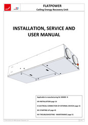
Zehnder Rittling FLATPOWER 1300 Installation, Service And User Manual (76 pages)
Ceiling Energy Recovery Unit
Brand:
Zehnder Rittling
| Category:
Heating System
| Size: 9.25 MB
Table of Contents
Table of Contents
2
Technical Specifications
5
Electrical Performance Data
5
Weights and Dimensional Data
5
General
7
Upon Receipt of the Material
9
III.1. Quality Check
9
III.2. Unpacking
9
III.3. Storage
9
End of Service Life
9
Packaging and Packages
9
Identification and Labelling
10
Overview and Construction
12
VII.1. General Overview of the Unit
12
VII.2. Sliding Electric Board
14
VII.3. Control Terminals and User Connections
15
Installation
16
VIII.1. Handling
16
VIII.2. Permitted Installation Configurations and Precautions to be Taken
17
VIII.3. Horizontal Lifting
17
VIII.3.A. Fixing the Frame to the Ceiling
18
VIII.3.B. Positioning the Unit on the Fixing Frame
19
VIII.3.C. Installation of the Unit Offset from the Ceiling
21
VIII.4. Access Inside the Unit
22
VIII.5. Access to the Sliding Electric Board and User Touch Control
23
VIII.6. Connection of the Supply Pressure Tap (LOBBY)
24
VIII.7. Installation of Filters Clogging Manometer
24
VIII.8. Connection to the Air Network
26
VIII.9. Motorised Shutoff Dampers (Optional)
26
VIII.10. Connection of Power Supply
27
Condensate Evacuation
28
IX.1. Evacuation by Gravity - General
28
IX.2. Plates Heat Exchanger Siphon
28
IX.3. Remote Coil Siphon
29
IX.4. CO or DXR Coils Condensate Siphon
29
IX.4.A. FLATPOWER 600
29
IX.4.B. FLATPOWER 1300
29
IX.5. Condensate Evacuation with Condensate Lift Pump (Optional)
30
IX.5.A. General Information
30
IX.5.B. Overview of the Condensate Lift Pump Kit
30
IX.5.C. Operating Principle
31
IX.5.D. Maintenance
31
IX.5.E. Performances and Operating Limits
31
Electrical Connection of External Devices
31
Remote Control of Low-Speed Forced Operation (Reduced Operation)
31
Remote Control of High-Speed Forced Operation (Normal Operation)
32
Remote Stop Control
32
Remote Fire Protection Control
32
Control of Supply Shutoff Damper - RMS
33
Control of Extract Shutoff Damper - RMR
33
Night Overventilation (Night Cooling) Signal (LOBBY Version)
34
Alarm Output Signal
34
Remote Firefighter Stop - ADP
34
Autonomous Trigger Detector - DAD
35
Heat Exchanger Condensate Lift Pump (PRC)
35
CO / DXR Coils Condensate Lift Pump (PRC)
36
Integrated Co/Dxr Coils Connection
36
Connection of Remote Coils in Duct
37
XII.1. Remote Hot Water Coil
37
XII.2. Remote Cold Water Coil
38
XII.3. Remote Changeover Coil
40
XII.4. Remote Serial Hot Water + Cold Water Coils
41
XII.5. Remote Reversible Direct Expansion (DXR) Coil
42
XII.6. Offset of the Supply Air Temperature Sensor SSG
43
General Operation
43
XIII.1. Thermal Sequence Initialisation
43
XIII.2. Start up Sequence
44
XIII.3. Shutdown Sequence (Post-Ventilation)
44
Starting up
45
Maintenance
46
XV.1. Annual General Checking
46
XV.2. Checking Filters
46
XV.3. Removal and Refitting of the Exchanger Condensate Tray
46
XV.4. Removal and Refitting of the Heat Exchanger
48
XV.5. Removal and Refitting of CO/DXR Coil Condensate Tray
50
Troubleshooting - Maintenance
51
XVI.1. Connection and Setting of the Filter Control Pressure Switch
51
XVI.2. Connection and Setting of the Fan Feedback Pressure Switches (ECO and DIVA Versions)
52
XVI.3. Connection and Setting of the Pressure Transducers (LOBBY)
53
XVI.4. Connection of Pressure Transducers (MAC2)
54
XVI.5. Overheating Safety Thermostats THS and THSD
55
XVI.6. Frost Protection Thermostat THA
56
XVI.7. Replacing the Internal Memory Battery
57
Wiring Diagrams
57
XVII.1. Power Wiring Diagram -230V AC Single-Phase Power Supply
58
XVII.2. Power Wiring Diagram -400V AC 3-Phases Power Supply
59
XVII.3. Control Wiring Diagram - Pressure Transducers and CO2 Sensor
60
XVII.4. Control Wiring Diagram - Pressure Switches and Bypass Damper Actuator
61
XVII.5. Control Wiring Diagram - Temperature Sensors
62
XVII.6. Wiring Diagram - Fan Motors
63
General Wiring Diagram of Optional Customer's Equipment
64
Easy 5.0 Control
66
Season Control
66
XX.1. General
66
XX.2. Overview and Constitution
66
XX.3. Electrical Compartments and User Controls
67
XX.4. General Operating Principle
68
XX.5. User Setting Commands
68
XX.5.A. Thermostat TH1 (Heat Recovery)
68
XX.5.B. Thermostat TH2 (Cold Recovery)
68
XX.5.C. Thermostat TH3 (Frost Protection)
68
XX.6. Connecting and Setting External User Devices
69
XX.7. Troubleshooting and Maintenance
69
XX.8. General Wiring Diagram of the SEASON Control System
70
XX.8.A. FLATPOWER SEASON 600-900
70
XX.8.B. FLATPOWER SEASON 1300 - 1800 - 2500
71
Aeraulic Performance Curves
72
Commissionning Report
74
Advertisement
Advertisement
Related Products
Zehnder Rittling Comfoair 140
Zehnder Rittling FLATPOWER 1800
Zehnder Rittling FLATPOWER
Zehnder Rittling FLATPOWER 600
Zehnder Rittling FLATPOWER 900
Zehnder Rittling FLATPOWER 2500
Zehnder Rittling ComfoAir 180
Zehnder Rittling ComfoAir 155 WM
Zehnder Rittling ComfoAir 185 WM
Zehnder Rittling Eversky 1100
Zehnder Rittling Categories
Fan
Heater
Industrial Equipment
Air Handlers
Control Unit
More Zehnder Rittling Manuals
Login
Sign In
OR
Sign in with Facebook
Sign in with Google
Upload manual
Upload from disk
Upload from URL