Sign In
Upload
Manuals
Brands
Toshiba Manuals
Air Conditioner
MiNi-SMMS MCY-MAP0601HT
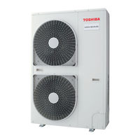
Toshiba MiNi-SMMS MCY-MAP0601HT Manuals
Manuals and User Guides for Toshiba MiNi-SMMS MCY-MAP0601HT. We have
5
Toshiba MiNi-SMMS MCY-MAP0601HT manuals available for free PDF download: Service Manual, Installation Manual, Owner's Manual
Toshiba MiNi-SMMS MCY-MAP0601HT Service Manual (194 pages)
Mini-SUPER MODULAR MULTI SYSTEM
Brand:
Toshiba
| Category:
Air Conditioner
| Size: 6.1 MB
Table of Contents
Service Manual
1
Warnings on Refrigerant Leakage
2
Check of Concentration Limit
2
Table of Contents
3
Safety Caution
4
Confirmation of Warning Label on the Main Unit
4
Explanation of Illustrated Marks
4
Cautions on Installation/Service
7
New Refrigerant (R410A)
7
Pipe Materials
7
Safety Caution Concerned to New Refrigerant
7
Tools
8
Environmental Concern
9
Recharge of Refrigerant
9
Allocation Standard of Model Name
10
Design Methods
10
Outdoor Units
10
System Overview
10
Indoor Units
11
Branching Joints and Headers #1
13
PMV Kit
13
Remote Controller
14
Remote Controllers
17
4-Way Air Discharge Cassette Type
18
Indoor Unit
18
Wiring Diagram
18
2-Way Air Discharge Cassette Type
19
1-Way Air Discharge Cassette Type (Compact Type)
20
Concealed Duct Standard Type
22
Concealed Duct High Pressure Type
23
Under Ceiling Type
24
High Wall Type
25
Floor Standing Cabinet Type
27
Floor Standing Concealed Type
28
Floor Standing Type
29
Slim Duct Type
30
Outdoor Unit
31
Connection of PMV Kit
32
Compact 4-Way Air Discharge Cassette Type
33
Parts Rating
33
Parts Unit
33
Way Air Discharge Cassette Type
34
Concealed Duct High Static Pressure Type
35
Floor Standing Type
36
High Wall Type
36
Under Ceiling Type
36
Outdoor Unit
37
Parts Layout in Outdoor Unit
38
Name of each Part
39
Display Section
40
Parts Name of Remote Controller
40
Correct Usage
41
Operation Section
41
Remote Controller Sensor
41
Adjustment of Wind Direction
42
How to Set up the Air Direction
42
Adjustment of Air Flow Direction Rightwards/Leftwards
43
Adjustment of Air Flow Direction Upwards/Downwards
43
How to Adjust the Air Flow Direction, Using the Swinging Function
43
Setup of Air Flow Direction and Swinging Function
43
How to Change the Air Outlet Port
44
Right/Left Air Direction Adjustment
44
Setup of Air Direction and Swinging
44
Timer Operation
45
Electric Wiring
46
Installation
46
Installation Location
46
Maintenance
46
Cleaning of the Main Unit / Remote Controller
47
Re-Installing the Air Filter
47
Air Conditioner Operations and Performance
48
Hints for Economical Operation
48
Re-Installation
49
When the Following Symptoms Air Found
49
Confirmation and Check
50
Confirmation of Error History
50
Refrigerant Cycle Diagram
51
Refrigerant Piping Systematic Drawing
51
Explanation of Functional Parts
52
Indoor Unit
53
Setup Method
54
Switch (SW08) Set up of the Outdoor Unit
54
Control Outline
55
Operation Start/Operation End
59
Other Cautions
62
Applied Control
63
Setup of Selecting Function in Indoor Unit
63
Function Selecting Item Code (DN)
64
Indoor Unit Capacity
65
Applied Control in Indoor Unit
66
Remote Location ON/OFF Control Box (TCB-IFCB-4E)
66
Ventilating Fan Control from Remote Controller
67
Demand Control from Indoor Unit
68
Leaving-ON Prevention Control
68
Applied Control in Outdoor Unit
69
Connector Position Detail
69
Outdoor Unit Interface P.C. Board
69
Switch Position Detail
69
Placing Position
70
Wiring
70
Feature
71
Function / Electric Wiring Diagram
71
Power Peak-Cut Control
71
External Master ON/OFF Control
73
Night Operation (Sound Reduction) Control
74
Operation Mode Selection Control
75
Error Output Control
76
How to Use
77
Image of Installation
77
PMV Kit out Line
77
Purpose of Using
77
Effect of Connecting PMV Kit Without Fully Opening of Indoor Unit PMV
78
How to Fully Open PMV of Indoor Unit
78
Procedure and Summary of Test Operation
79
Test Operation
79
Check Lists
80
Address Setup
81
Cautions
81
Check at Main Power-ON
81
Check on Outdoor and Indoor Unit
81
Address Setup Procedure
82
Automatic Address Setup
82
Manual Address Setup from Remote Controller
83
Change of Indoor Address from Remote Controller
84
Confirmation of Indoor Unit Address and Position by Using the Remote Controller
84
Clearance of Address
85
Check after Address Setup When Central Control System Is Connected
86
In Case of Increase the Address-Undefined Indoor Units (Extension, Etc.)
86
A Check Code Is Displayed on the Remote Controller
87
Troubleshooting in Test Operation
87
In Check for No. of Connected Outdoor Units and Connected Indoor Unitsafter Address Setup, Diminished No. of Connected Units Displayed.(There Are Outdoor/Indoor Units Which Do Not Operate in a Test Operation.)
88
Operation from Remote Controller Is Not Accepted and a Check Code Is Dis-Played on 7-Segment Display of the Interface P.C. Board of the Outdoor Unit
88
There Is no Display of a Check Code on 7-Segment Display on the Interfacep.C. Board of the Outdoor Unit Though There Is Indoor Unit Which Does Notaccept the Operation from the Remote Controller
88
Incorrect Wiring Example
89
Cooling/Heating Test Operation Check
90
Fan Operation Check
90
Test Operation Check
90
Test Operation Start/Stop Operation
90
Wireless Remote Controller
91
In Case of Wireless Remote Controller(for under Ceiling Type and 1-Way Air Discharge Cassette Type (2 Series))
92
Function to Start/Stop (ON/OFF) Indoor Unit from Outdoor Unit
95
Service Support Function
95
Cooling Test Operation Function
96
Heating Test Operation Function
96
Operation Procedure
96
Batch Start/Stop (ON/OFF) Function
97
Individual Start/Stop (ON/OFF) Individual Test Operation Function
98
Clearing from the Main Remote Controller
99
Error Clearing Function
99
Clearing from the Interface P.C. Board
100
Clearing of Error Check Code by Power Reset
100
Distinction Procedure
101
Remote Controller Distinction Function
101
Pulse Motor Valve (PMV) Forced Open Fully/Close Fully Function in Outdoor Unit
102
Pulse Motor Valve (PMV) Forced Open/Close Function in Indoor Unit
102
Solenoid Valve Forced Open/Close Function in Outdoor Unit
103
Fan Operation Check in Outdoor Unit
104
Manual Adjustment Function of Outside Temp (TO) Sensor
105
Service Support Function List
105
Indoor Fan Only Operating Mode
106
Indoor Fan Operation Check Function
106
Calling of Display Screen
107
Monitor Function of Remote Controller Switch
107
Troubleshooting Summary
108
Troubleshooting
108
Check Method
109
Check Code List
109
Error Detected by TCC-LINK Central Control Device
111
Special Mention
112
New Check Code
112
Difference between the TCC LINK and AI-NET Check Code
112
In Case of Wired Remote Controller (RBC-AMT31E)
113
Troubleshooting by Check Display on Remote Controller
113
In Case of Central Remote Controller (TCB-SC642TLE)
114
In Case of AI-NET Central Remote Controller
115
Check Code and Check Position Displayed on the Remote Controller and Outdoor Unit (7-Segment Display of Interface)
116
Error Detected by AI-NET Central Control Device
124
Diagnosis Procedure for each Check Code
125
How to Read the Check Display
144
7-Segment Display Function
144
Check Procedure When the System Has Stopped Due to an Trouble
144
7-Segment Display on the Outdoor Unit (Interface P.C. Board)
144
Data Display of System Information
145
Data Display of Outdoor Unit Information
146
Data Display of Outdoor Cycle
147
Data Display of Indoor Unit Information
147
Temperature Sensor Characteristics
148
7-Segment Display A, B
148
Outdoor EEPROM Check Code Display
148
Sensor Characteristics
148
Pressure Sensor Characteristics
149
Pressure Sensor Output Check
150
Pd Sensor Characteristics
150
Ps Sensor Characteristics
151
Indoor Controller Block Diagram
152
Connection of Wired Remote Controller
152
Configuration of Control Circuit
152
Connection of the Wireless Remote Controller Kit
154
Connection of both Remote Controller and Wireless Remote Controller Kit
156
Indoor P.C. Board
158
Optional Connector Specifications of Indoor P.C. Board
161
Positions to be Checked on the Interface P.C. Board (MCC-1429)
162
Inverter P.C. Board (MCC-1535) (IPDU1)
163
Fan P.C. Board (MCC-1531) (Fan IPDU)
164
Noise Filter P.C. Board (MCC-1551)
164
Outdoor Interface P.C. Board
165
Dip Switch Function Exchange Setup List
165
Backup Operations (Emergency Operation)
166
Vacuuming
167
Compressor Replacing Procedure (Outline)
167
Replacing Compressor
167
Replacing Procedure of Parts
168
Refrigerant Recovery in Outdoor Unit
181
P.C.board
182
Exchange of P.C. Board for Indoor Service
182
Requirement When Exchanging the P.C. Board Assembly for Indoor Service
182
Exchange Procedure
182
Readout Setup Contents from EEPROM
183
Exchange of P.C. Board for Service
184
Writing-In of Setup Contents to EEPROM
185
EEPROM Layout
185
Record the Contents of the Following before Exchanging P.C. Boards. (Item Code List)
186
Printed Circuit Board (P.C. Board) Replace Procedure Manual
187
Mini-SMMS Unit
188
Exploded Views and Parts List
188
Refrigeration Circuit
189
Controller for Air Conditioner
190
Refrigeration Circuit Diagram
191
Advertisement
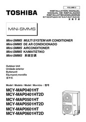
Toshiba MiNi-SMMS MCY-MAP0601HT Installation Manual (160 pages)
Multi System Air Conditioner, Outdoor Unit
Brand:
Toshiba
| Category:
Air Conditioner
| Size: 6.55 MB
Table of Contents
Accessory Parts
0
Safety Caution
0
Installation of New Refrigerant Air Conditioner
0
Selection of Installation Place
0
Refrigerant Piping
0
Electric Wiring
0
Installation of Outdoor Unit
0
Address Setup
0
Troubleshooting
2
Table of Contents
3
Peças Acessórias
4
Precaução de Segurança
4
Instalação de Ar Condicionado de Novo Refrigerante
6
Selecção Do Local de Instalação
7
Tubagem de Refrigerante
11
Ligações Eléctricas
23
Instalação da Unidade Exterior
29
Definição Do Endereço
30
Operação de Teste
39
Resolução de Problemas
41
Aandachtspunten Voor Uw Veiligheid
43
Accessoires
43
Installeren Van Een Airconditioner Met Nieuw Koelmiddel
45
De Installatielocatie Bepalen
46
Koelmiddelleidingen
50
Elektrische Aansluitingen
62
De Buitenunit Installeren
68
Adres Instellen
69
Werkingstest
78
Storingen Verhelpen
80
Ðáñåëêïìåíá Áîåóïõáñ
82
Ðñïöõëáîåéó Ãéá Ôçí Áóöáëåéá
82
Åãêáôáóôáóç Êëéìáôéóôéêïõ Ìå Íåï Øõêôéêï
84
Åðéëïãç Èåóçó Åãêáôáóôáóçó
85
Óùëçíùóç Øõêôéêïõ
89
Çëåêôñéêåó Óõíäåóåéó
101
Åãêáôáóôáóç Ôçó Åîùôåñéêçó Ìïíáäáó
107
Ñõèìéóç Äéåõèõíóçó
108
Äïêéìç Ëåéôïõñãéáó
117
Áíôéìåôùðéóç Âëáâùí
119
Toshiba MiNi-SMMS MCY-MAP0601HT Installation Manual (81 pages)
Mini-SMMS MULTI SYSTEM
Brand:
Toshiba
| Category:
Air Conditioner
| Size: 2.96 MB
Table of Contents
English
3
Table of Contents
3
Accessory Parts
4
Safety Caution
4
Installation of New Refrigerant Air Conditioner
6
Selection of Installation Place
7
Installation Place
8
Refrigerant Piping
11
Air Purge
20
Electric Wiring
23
Connection of Power Supply
24
Installation of Outdoor Unit
29
Address Setup
30
Test Operation
39
Troubleshooting
41
German
43
Zubehör
43
Sicherheitshinweise
43
Installation von Klimageräten mit Modernen Kältemitteln
45
Auswahl des Aufstellungsortes
46
Kältemittelleitungen
50
Elektrische Verdrahtung
62
Installation der Ausseneinheit
68
Adress-Einstellung
69
Testlauf
78
Fehlersuche
80
Advertisement
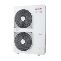
Toshiba MiNi-SMMS MCY-MAP0601HT Installation Manual (28 pages)
MULTI TYPE
Brand:
Toshiba
| Category:
Air Conditioner
| Size: 4.98 MB
Table of Contents
Installation Manual
1
Outdoor Unit
1
Table of Contents
2
Precautions for Safety
3
Accessory Parts
5
Installation of New Refrigerant Air Conditioner
5
Selection of Installation Place
6
Refrigerant Piping Connection
7
Refrigerant Piping
8
Air Purge
12
Electric Wiring
14
Connection of Power Supply
15
Installation of Outdoor Unit
17
Address Setting
18
Address Setup Procedure
19
Test Run
23
Troubleshooting
24
Toshiba MiNi-SMMS MCY-MAP0601HT Owner's Manual (24 pages)
AIR CONDITIONER Multi Type
Brand:
Toshiba
| Category:
Air Conditioner
| Size: 1.44 MB
Table of Contents
Outdoor Unit
1
Table of Contents
2
Precautions for Safety
3
Part Names
5
Way Cassette Type
6
Ceiling Type
6
Part Names and Functions of the Remote Controller
7
Operation Section
8
Correct Usage
9
Timer Operation
10
Installation
11
Notes on Operations and Performance
11
Louver Direction
12
Floor Standing Type
16
Tips for Saving Energy and Comfortable Performance
17
Maintenance
18
When the Following Symptoms Are Found
19
Specifications
20
Declaration of Conformity
21
Advertisement
Related Products
Toshiba MiNi-SMMS MCY-MAP0401HT
Toshiba MiNi-SMMS MCY-MAP0501HT
Toshiba MiNi-SMMS MCY-MAP0401HT2D
Toshiba MiNi-SMMS MCY-MAP0501HT2D
Toshiba MiNi-SMMS MCY-MAP0601HT2D
Toshiba MiNi-SMMS RBM-PMV0361E
Toshiba MiNi-SMMS RBM-PMV0901E
Toshiba MiNi-SMMS
Toshiba MMY-MAP0804FT8Z-E
Toshiba MMK-AP0183H-CMMK-AP0243H
Toshiba Categories
Laptop
Air Conditioner
TV
LCD TV
All in One Printer
More Toshiba Manuals
Login
Sign In
OR
Sign in with Facebook
Sign in with Google
Upload manual
Upload from disk
Upload from URL