Sign In
Upload
Manuals
Brands
Raisecom Manuals
Switch
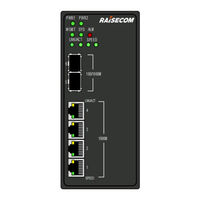
Gazelle S1020i4GF-8GE-PWHGL-DC48
Raisecom Gazelle S1020i4GF-8GE-PWHGL-DC48 Manuals
Manuals and User Guides for Raisecom Gazelle S1020i4GF-8GE-PWHGL-DC48. We have
1
Raisecom Gazelle S1020i4GF-8GE-PWHGL-DC48 manual available for free PDF download: User Manual
Raisecom Gazelle S1020i4GF-8GE-PWHGL-DC48 User Manual (83 pages)
Brand:
Raisecom
| Category:
Switch
| Size: 1.48 MB
Table of Contents
Table of Contents
5
1 Overview
12
Introduction
12
Characteristics
13
Figure 1-1 Appearance of the Gazelle S1020I-2GF-4GE-PWH-GL-DC48
13
Features
14
Table 1-1 Features
14
Applications
15
Crossroad Video Monitoring System Application
15
Product Model
16
Figure 1-2 Crossroad Video Monitoring System for Expressway Vehicles
16
Table 1-2 Models of the Gazelle S1020I-GL
16
2 Hardware Structure
18
Appearance
18
Gazelle S1020I-2GF-4GE-PWH-GL-DC48
18
Figure 2-1 Front Appearance of the Gazelle S1020I-2GF-4GE-PWH-GL-DC48
19
Table 2-1 Front Panel of the Gazelle S1020I-2GF-4GE-PWH-GL-DC48
19
Gazelle S1020I-4GF-8GE-PWH-GL-DC48
20
Figure 2-2 Top Appearance of the Gazelle S1020I-4GF-8GE-GS
20
Figure 2-3 Front Appearance of the Gazelle S1020I-4GF-8GE-PWH-GL-DC48
21
Table 2-2 Front Panel of the Gazelle S1020I-4GF-8GE-PWH-GL-DC48
21
Gazelle S1020I-2GF-4GE-GL
22
Figure 2-4 Top Appearance of the Gazelle S1020I-4GF-8GE-PWH-GL-DC48
22
Figure 2-5 Front Appearance of the Gazelle S1020I-2GF-4GE-GL-DCW48
23
Table 2-3 Front Panel of the Gazelle S1020I-4GF-8GE-PWH-GL-DCW48
23
Figure 2-6 Top Appearance of the Gazelle S1020I-2GF-4GE-GL-DCW48
24
Figure 2-7 Front Appearance of the Gazelle S1020I-2GF-4GE-GL-AC
25
Table 2-4 Front Panel of the Gazelle S1020I-2GF-4GE-GL-AC
25
Gazelle S1020I-4GF-8GE-GL
26
Figure 2-8 Top Appearance of the Gazelle S1020I-2GF-4GE-GL-AC
26
Figure 2-9 Front Appearance of the Gazelle S1020I-4GF-8GE-GL-DCW48
27
Table 2-5 Front Panel of the Gazelle S1020I-4GF-8GE-PWH-GL-DCW48
27
Figure 2-10 Top Appearance of the Gazelle S1020I-4GF-8GE-GL-DCW48
28
Figure 2-11 Front Appearance of the Gazelle S1020I-4GF-8GE-GL-AC
29
Table 2-6 Front Panel of the Gazelle S1020I-4GF-8GE-GL-AC
29
Interfaces
30
Interface Types and Usage
30
Figure 2-12 Top Appearance of the Gazelle S1020I-4GF-8GE-GL-AC
30
Table 2-7 Interface Types and Usage
30
Table 2-8 Power and Management Interfaces
31
Button
32
Interface Properties
32
1000BASE-X SFP Optical Interface
32
10/100/1000BASE-T Electrical Interface
32
Table 2-9 Button of the Gazelle S1020I-GL
32
Table 2-10 Parameters of the 1000BASE-X SFP Optical Interface
32
Table 2-11 Parameters of the 10/100/1000BASE-T Electrical Interface
32
Console Interface
33
Alarm Output Interfaces
33
Table 2-12 Parameters of the Console Interface
33
Figure 2-13 Alarm Output Interface 1
34
Figure 2-14 Alarm Output Interface 2
34
Table 2-13 Parameters of the Alarm Output Interface
34
DI Interface
35
Figure 2-15 DI Interface 1
35
Figure 2-16 DI Interface 2 (for the Gazelles1020I-4GF-8GE-GL Only)
35
Table 2-14 Digital Input Interface
35
Leds
36
Table 2-15 Configuring Triggering Condition
36
Table 2-16 Parameters of the DI Interface
36
Table 2-17 Leds
36
Power Supply
37
Introduction
37
Appearance and Interfaces
38
Figure 2-17 DC Power Interface 1
38
Figure 2-18 DC Power Interface 2
38
Table 2-18 Terminals on DC Power Interface 1
38
Figure 2-19 Appearance of the AC Power Interface on the Gazelle S1020I-2GF-4GE-GL-AC
39
Figure 2-20 Appearance of the AC Power Interface on the Gazelle S1020I-4GF-8GE-GL-AC
39
Table 2-19 Terminals on DC Power Interface 2
39
Table 2-20 Interface Type and Usage of the AC Power Supply
39
Specifications
40
Lookup Table of Optical Module Parameters
40
Table 2-21 Specifications of DC Power Supplies
40
Table 2-22 Parameters of the GE (1250 Mbit/S) Dual-Fiber Bidirectional Optical Module
40
Cables
41
Ground Cable
41
Table 2-23 Parameters of the GE (1250 Mbit/S) Single-Fiber Bidirectional Optical Module
41
Figure 2-21 Ground Cable
42
Figure 2-22 OT Terminal
42
Table 2-24 Technical Specifications of the Ground Cable
43
Table 2-25 Technical Specifications of the OT Terminal
43
Console Cable
44
Figure 2-23 RJ45 Console Cable
44
Figure 2-24 Pins and Wiring
44
Ethernet Cable
45
Figure 2-25 Ethernet Cable
45
Table 2-26 Technical Specifications of the Console Cable
45
Figure 2-26 Wiring of the Straight-Through Cable
46
Table 2-27 Wiring of EIA/TIA 568A and EIA/TIA 568B Standards
46
DC Power Cables
47
Figure 2-27 Wiring of the 100 Mbit/S Crossover Cable
47
Table 2-28 Technical Specifications of the Cable
47
Figure 2-28 DC Power Connector
48
Figure 2-29 DC Power Connector
48
Table 2-29 Technical Specifications of DC Power Cable 1
48
AC Power Cable
49
Figure 2-30 European AC Power Cable
49
Table 2-30 Technical Specifications of DC Power Cable 2
49
Table 2-31 AC Power Cables of the Gazelle S1010I-2GF-4GE-GL
49
Figure 2-31 American AC Power Cable
50
Table 2-32 Technical Specifications of the European AC Power Cable
50
Table 2-33 Technical Specifications of the American AC Power Cable
50
Fiber
51
Table 2-34 Type and Usage of the Fiber
51
Figure 2-32 LC/PC Fiber Connector
52
Table 2-35 Wiring of the Fiber
52
3 Technical Specifications
53
Overall Parameter
53
Table 3-1 Overall Parameters of the Gazelle S1020I-GL
53
Compliance Standards
54
Environmental Standards
54
Table 3-2 Environmental Requirements
54
Technical Specifications
55
Laser Safety Class
55
Reliability Indicators
55
EMC Standards
55
Table 3-3 Reliability Indicators
55
4 Hardware Installation
57
Preparing for Installation
57
Precautions
57
Environmental Conditions
57
Power Supply Conditions
58
Static Electricity Conditions
58
Grounding Conditions
58
Other Conditions
58
Table 4-1 Requirements for the Operating Environment
58
Table 4-2 Power Supply Requirements for Operation
58
Installing Device
59
Installing Device on Guide Rail
59
Figure 4-1 Connecting the Rail Clip to the Guide Rail
59
Grounding Device
60
Figure 4-2 Installing the Device on the Guide Rail
60
Connecting Cables
61
Connecting Ethernet Cable
61
Figure 4-3 Loosen the Screw of the Ground Terminal
61
Figure 4-4 Connecting the Ground Cable
61
Connecting Fiber
62
Figure 4-5 Connecting the Ethernet Cable
62
Figure 4-6 Inserting the Optical Module
62
Connecting Power Cable
63
Figure 4-7 Inserting the Fiber
63
Powering on Device
64
Checking Installation
64
Figure 4-8 Connecting the DC Power Connector
64
Table 4-3 Items to be Checked after Installation
64
5 Management and Maintenance
66
Management Modes
66
Cli
66
SNMP Mode
67
Maintenance Modes
67
Ping
67
Traceroute
67
Environment Monitoring
68
RMON Management
68
Watchdog
68
Port Mirroring
68
Nview NNM System
68
Functions
68
Features
69
Figure 5-1 Location of the Nview NNM System
70
6 Appendix
71
Terms
71
Acronym and Abbreviations
76
Advertisement
Advertisement
Related Products
Raisecom Gazelle S1020i4GF-8GE-GLAC
Raisecom Gazelle S1020i4GF-8GE-GLDCW48
Raisecom Gazelle S1020i-GL Series
Raisecom Gazelle S1020i2GF-4GE-PWHGL-DC48
Raisecom Gazelle S1020i2GF-4GE-GLAC
Raisecom Gazelle S1020i2GF-4GE-GLDCW48
Raisecom Gazelle S1020i-LI
Raisecom Gazelle S1000i-LI
Raisecom Gazelle S1000i2GF-4FE-LI
Raisecom Gazelle S1000i4GF-16FE-LI
Raisecom Categories
Multiplexer
Switch
Network Hardware
Media Converter
Network Router
More Raisecom Manuals
Login
Sign In
OR
Sign in with Facebook
Sign in with Google
Upload manual
Upload from disk
Upload from URL