Sign In
Upload
Manuals
Brands
Parker Manuals
DC Drives
590+ series
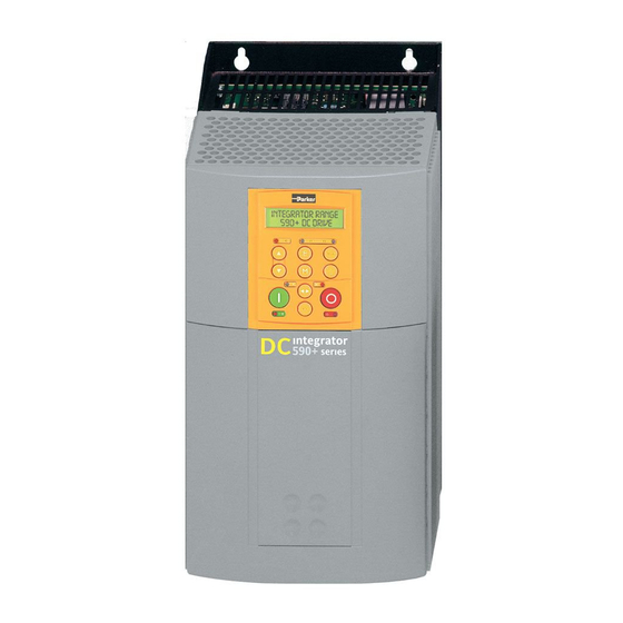
Parker 590+ series Manuals
Manuals and User Guides for Parker 590+ series. We have
1
Parker 590+ series manual available for free PDF download: Product Manual
Parker 590+ series Product Manual (546 pages)
Brand:
Parker
| Category:
DC Drives
| Size: 17.22 MB
Table of Contents
Safety Information
4
Application Area
5
Intended Users
5
Hazards
6
Product Warnings
6
Emc
7
Safety
7
Application Risk
8
Risk Assessment
8
Table of Contents
9
Chapter 1 Getting Started
15
About this Manual
17
How the Manual Is Organised
17
Initial Steps
17
Equipment Inspection and Storage
18
Packaging and Lifting Details
18
Operation
18
Programming (Keypad or Suitable PC Programming Tool Only)
18
CHAPTER 2 Product Overview
19
Product Range
21
Control and Communications
21
Regenerative and Non-Regenerative Models
21
Field Regulator
21
Output Currents (Armature)
22
590+ Controller (Frames 1 & 2)
23
590+ Controller (Frame 3)
24
590+ Controller (Frames 4 & 5)
25
590+ Controller (Frame 6)
26
590+ Product (Frame H)
27
590+ Door Assembly (Frames 3, 4, 5, 6 & H)
28
How It Works
29
Control Features
30
Keypads
31
Option Boards
31
CHAPTER 3 Installing the Drive
33
Mechanical Installation
35
Unpacking the Drive
35
Lifting the Drive
35
Dimensions Diagrams
36
Mounting the Drive
39
Recommended Tools
39
Ventilation and Cooling Requirements
40
Installing the Fan (Frame H)
40
Installing the External Vent Kit (Frames 4 & 5)
41
AC Line Choke
41
Filtering
42
AC Line Choke and Capacitors Fitted to Frame 1 - Diagram
42
Electrical Installation
43
Cabling Requirements
43
Cable Gland Requirements
44
Cable and Screen Fixings
44
Degree Screened Connection
44
Minimum Connection Requirements
45
Power Cables
46
Control Wiring
46
Important Connections
46
Connection Diagrams
47
Power Connections: Frames 1, 2, 3 & 4 (General Purpose Configuration)
47
Power Connections: Frame 5 (`General Purpose’ Configuration)
48
Power Connections: Frame 6 (`General Purpose’ Configuration)
49
Power Connections: Frame H (`General Purpose’ Configuration)
50
Power Connections
51
3-Phase Supply, 3-Phase External Contactor
51
Protective Earth Connections
53
Motor Armature
53
Motor Field
54
Motor Thermistor
54
External AC Field
55
Auxiliary Supply
55
Control Connections
56
Ramp Speed Setpoint
56
Current Limit
57
Program Stop/Coast Stop
57
Enable
58
Start/Run
58
Jog/Slack
58
External Trip
59
Drive Healthy
59
Digital Outputs
59
Direct Speed Setpoints
60
Auxiliary Current Clamp (-Ve)
60
Analog Outputs
61
Current Meter Output
61
Digital Inputs
61
Analog Tachometer
62
Microtach
62
Wire-Ended Encoder
63
Technology Box Option
63
Motor Field Options
64
Internal/External Supply (Frames 2, 3, 4 & 5)
64
Terminal Board - PCB Reference 470330 (Frame 2)
65
Internal Motor Field (Default for this Board)
65
External Motor Field Connections
65
Power Board - PCB Reference 385851 (Frame 3)
66
Re-Wiring Procedure
66
Power Board – PCB Reference 466701 (Frames 4 & 5)
67
DC Contactor - External Va Sensing
68
Power Board - PCB Reference 385851 (Frame 3)
68
Power Board - PCB Reference 466701 (Frames 4 & 5)
69
External Connections (Frames 6 & H)
70
Power Board Circuit Descriptions
71
AH470280U001, U002, U003, U004 (Frame 1)
71
590+ Power Board 4 Quad Diagram
71
Terminal Board - AH466407 Diagram
72
Connection Diagram for Power Board and Terminal Board AH470280 (Fr 1)
72
AH470330 (Frame 2)
73
16 590+ Power Board 4 Quad (AH470330) Diagram
73
AH470330 (Frame 2) Diagram
74
AH385851U002, U003, U004, U005 (Frame 3)
75
591 Power Board 2 Quad (AH385851U003, U004) Diagram
75
Heatsink Cooling Fan Connections
76
Contactor Supply
76
2 Quad Power Circuit - Using AH385851U003, U004 (Frame 3) Diagram
77
590 Power Board 4 Quad (AH385851U002, U005) - (Frame 3) Diagram
78
4 Quad Power Circuit - Using AH385851U002, U005 (Frame 3) Diagram
79
AH466701U001, U002, U003 (Frames 4 & 5)
80
590+/591+ Power Board Diagram
80
4 Quad Power Circuit – Frame 4 & 5 Units Using AH466701 Diagram
81
2 Quad Power Circuit – Frame 4 & 5 Units Using AH466701 Diagram
82
AH469419 (Frame 6)
83
AH466001U001, U101 (Frame H)
84
2 Quad Power Circuit – Frame 6 and Frame H Units Using AH466001U001
85
4 Quad Power Circuit – Frame 6 & Frame H Units Using AH466001U001
86
Optional Equipment
87
Remote Mounting the Keypad
87
6052 Mounting Kit Parts for the Remote Keypad - Tools Required
88
Assembly Procedure
89
Mounting Dimensions for the Remote-Mounted Keypad
89
Speed Feedback and Technology Options
90
Removal
90
Speed Feedback Option Boards
91
Microtach Option Board
91
Wire-Ended Encoder Option Board
91
Tacho Calibration Option Board
92
Combined Tacho and Encoder Feedback
92
Communications Technology Options
93
COMMS Option Technology Box
93
External AC Supply EMC Filter Installation
94
Cubicle-Mounting the DC590+ Drive with Filter
94
Connection Details
94
Earthing Details
95
Operating Conditions
95
Earth Fault Monitoring Systems
96
Frame 6: Assembly and Installation
97
Cubicle Details
98
Cooling
98
Assembly
99
Moving the AC Supply Terminals
101
Mounting the Phase Assemblies
102
Backplate Drilling Procedure
103
Connecting the Fishplates
103
Temporary Hanging Bolts
104
Offering-Up the Phase Assemblies
104
Tightening the Drive
105
Fitting the Control Panel Assembly
105
Terminal Connections
106
Electrical Installation (Frame 6)
107
Frame H: Additional Information
108
Removing the Cover (Frame H)
108
Changing DC Output Terminals (Frame H)
108
Drive Installation Drawings
109
Frame 1: 15A & 35A Stack Assembly – Drg. No. HG466465 Diagram
109
Frame 2: 40A-165A Stack Assembly Diagram
110
Frame 3: 180A Stack Assembly - Drg No. HG466427 Diagram
111
Frame 3: 270A Stack Assembly - Drg No. HG466428 Diagram
112
Frame 4: 380-830A Stack Assembly – Drg. No. HG466700U001 Diagram
113
Fr. 4: 380-830A External Vent Kit Installation – Drg No.hg466700U002
114
Frame 5: 1580A Stack Assembly – Drg No. HG466700U110 Diagram
115
Frame 5: 1580A External Vent Kit Inst. – Drg No.hg466700U111 Diagram
116
Frame H: 1200A-2700A Stack Assembly - Drg No.hg466432U000/1
117
Frame H : 1200A-2700A Stack Assembly - Drg No. HG466432U000/2 Diagram
118
Frame H: 1200A-2700A Stack Assembly - Drg No. HG466433U000/1 Diagram
119
Frame H: 1200A-2700A Stack Assembly - Drg No. HG466433U000/2 Diagram
120
Filter Installation Drawings
121
Filter Mounting Details, Part No. CO467844U015 for Frame 1: 15 Amp
121
Filter Mounting, Part No.co467844U040 for Fr. 1: 35 & Fr. 2: 40Amp
122
Filter Mounting Details, Part No. CO467844U070 for Frame 2: 70 Amp
123
Filter Mounting, Part No.co467844U110 for 590+ Frame 2: 110 Amp
124
Filter Mounting Details, Part No. CO467844U165 for Frame 2: 165 Amp
125
Filter Mounting Details, Part No. CO467844U180 for Frame 3: 180 Amp
126
Line Choke Installation Drawings
128
Line Choke (Frames 4, 5, 6 & H)
129
CHAPTER 4 Operating the Drive
131
Pre-Operation Checks
133
Prepare to Energise the Drive and System
133
Control Philosophy
134
Start/Stop and Speed Control
134
Selecting Local or Remote Control
135
LED Indications
135
Operation in Local Mode
136
Reading the Status Leds
136
Status Indications Given by the Health and Run Leds
136
Blank Cover Showing Leds
136
Setting-Up the Drive
137
Calibrating the Control Board
137
Selecting Speed Feedback
139
Speed Feedback Option Boards, Analog Tacho Calibration Option Board
139
Calibration of the New AH500935U001 Version
140
Calibration for Voltages Greater than 200V
140
Microtach and Encoder Feedback Option Boards
141
Initial Start-Up Routine
142
Step 1: Check the Speed Setpoints Operate Correctly
142
Step 2: Check the External Current Clamps
142
Step 3: Check the Speed Feedback Signals
142
Step 4: Select the Speed Feedback Method
143
Step 5: Start the Drive Using Auxiliary Power Only
143
6: Power-Down the Drive/Connect the 3-Phase Supply/Power-Up the Drive
143
Step 7: Set the Speed Setpoint(S) to 5%
144
Step 8: Check the MAIN CURR LIMIT Is Zero
144
Step 9: Start the Drive and Check the Field Voltage
144
Step 9.1 Internally Supplied Field
144
Step 9.2 Externally Supplied Field: (Not Available on Frame 1 Units)
145
Step 10: Check the Keypad
145
Step 11: Check the STANDSTILL LOGIC Parameter
145
Step 12: Turn the Motor and Check Direction of Rotation
146
Step 13: Check the Speed Feedback Sign
147
Step 14: Adjusting the Speed Setpoint
147
Step 14.1 4 Quadrant Drives Which Require Reverse Rotation
147
Step 14.2 Adjustment of ZERO SPEED OFFSET Parameter
147
Step 15: Fine Adjustments for Speed Feedback
148
Step 16: Adjustment for Field Weakening
148
Performance Adjustment
149
Current Loop - the ARMATURE Autotune Feature/Initial Conditions
149
Step 17: Adjustment for Reversing Drives
149
Step 18: Re-Setting the MAIN CURR. LIMIT Parameter
149
Performing an Autotune
150
Autotune Failed?
150
Speed Loop Adjustment
150
A Method for Setting-Up the PI Gains
151
Normal Stop (C3)
152
Starting and Stopping Methods
152
Time-Out in Normal Stop
154
Program Stop (B8)
155
Program Stop Timing
156
Time-Out in Program Stop
157
Normal Starting Method
158
Coast Stop (B9)
158
The Trip Condition
158
Advanced Starting Methods
159
Starting Several Drives Simultaneously
159
Jog
159
Crawl
159
Take up Slack
160
External Control of the Drive
161
Remote Sequencing Command
161
Useful Commands Using EI Bisynch ASCII - REM. Sequence
162
Sequence Status
163
Typical Bit Patterns Reported Via SEQ STATUS
163
CHAPTER 5 Control Loops
165
Control Loops - Principle of Operation
167
Current Loop
167
Adaptive Current Control
167
Back EMF (BEMF) Estimate
167
Manual Tuning
168
Bridge Changeover Delay
168
Speed Loop
170
Tuning Hints
170
Diagnostics
170
Current Demand Rate Limit (DI/Dt)
170
Field Control
171
Set-Up Notes/Initial Conditions
171
Field Weakening
172
Current Control
172
Voltage Control
172
Advanced Mode
173
Standby Field
173
CHAPTER 6 The Keypad
175
Connecting the 6911 Keypad
177
Control Key Definitions
178
Keys for Programming the Drive
178
Keys for Operating the Drive Locally
179
Indications
179
Keypad Alarm Messages
179
Keypad Leds
180
The Menu System
181
The Local Menu
182
The L/R Key
182
The PROG Key
182
Navigating the Menu System
183
Changing a Parameter Value
183
The Menu System Map
184
The Keypad Menus
186
Diagnostics (MMI Only)
186
Setup Parameters
191
Password
192
To Activate Password Protection
192
To Deactivate Password Protection
192
Menus
193
Selecting a Menu Viewing Level
193
Selecting the Display Language
193
Alarm Status
193
Serial Links
194
System
194
Software Parameter
194
Configure I/O Paramater
194
Configure Drive (MMI View)
195
Function Blocks
196
Menu Shortcuts and Special Key Combinations
197
Quick Tag Information
197
Changing the Stack Size (3-Button Reset)
197
Resetting to Factory Defaults (2-Button Reset)
198
Cloning Feature
198
How to Save, Restore and Copy Your Settings
199
Saving Your Application
199
Operating Mode (CONFIGURE ENABLE = DISABLED)
199
Configuration Mode (CONFIGURE ENABLE = ENABLED)
199
Restoring Saved Settings
200
Copying an Application
200
CHAPTER 7 Trips and Fault Finding
201
What Happens When a Trip Occurs
203
Drive Indications/Keypad Indications
203
Resetting a Trip Condition
203
Trips and Fault Finding
203
Fault Finding
204
Calibration Checks
205
Control Board Calibration
205
Power Board Current Calibration Switches (Frame 2)
205
Adaptor Board Current Calibration Switch (Frame 3)
206
IA CAL - Armature Current Calibration Switch
206
Power Board Current Calibration Switches (Frames 4 & 5)
206
Power Board Current Calibration Switches (Frames 6 & H)
207
IA CAL - Armature Current
207
Armature Voltage
207
IF CAL - Field Current
207
Adaptor Board Current Calibration Switch (Frames 6 & H)
208
Alarm Messages
209
Last Alarm
209
Health Word/Health Store
209
Alarm History
209
Hexadecimal Representation of Trips
210
Power Board LED Trip Information (Frame 4, 5, 6 & H)
211
Frame 4 LED Trip Information
211
Frame 5 LED Trip Information
212
Frame 6 LED Trip Information
213
Frame H LED Trip Information
214
Using the MMI to Manage Trips
215
Trip Messages
215
Overspeed
215
Field over I
215
Heatsink Trip
216
Thermistor
216
Over Volts (Va)
216
Encoder Failed
217
Phase Lock
217
Stall Trip
217
Over I Trip
217
Self Test Alarms
219
Sequencing F
219
Setting Trip Conditions
220
Viewing Trip Conditions
220
Inhibiting Alarms
220
Test Points
221
CHAPTER 8 Routine Maintenance and Repair
223
Maintenance
225
Service Procedures
225
Preventive Maintenance
225
Repair
226
Saving Your Application Data
226
Returning the Unit to Parker SSD Drives
226
Disposal
227
Technical Support Checks
227
Continuity Test on Fuses Using a Meter
228
Diode Check on Power Terminals Using a Meter
228
Internal Field Check Using a Meter
228
External Field Check Using a Meter
228
Repairs for Frames 4 & 5
229
Replacing the Fan (Frames 4 & 5)
229
Repairs for Frame 6
230
AC Fuse Replacement (Frame 6 Non-Regen Unit - 2Q)
230
DC Fuse Replacement (Frame 6 Regen Unit - 4Q)
231
Replacing a Phase Assembly (Frame 6)
233
Replacing a Fan (Frame 6)
234
Repairs for Frame H
235
Fuse Replacement (Frame H)
235
590+ 4Q Product (Regenerative)
235
Bench-Top Replacement Procedure
236
In-Situ Replacement Procedure
236
591+ 2Q Product (Non-Regenerative)
237
Phase Assembly Replacement (Frame H)
238
Front View of Phase Assemblies
239
Phase Assembly Removal Procedure
239
Phase Assembly Fitting Procedure
240
Serial Communications
241
System Port (P3)
243
Drive Connections
243
6-Way Lead to DB9/DB25 Connector
243
UDP Support
244
System Port (P3) Set-Up
244
UDP Transfer Procedure
244
MMI Dump Procedure
245
Dselite Support
246
5703 Support
247
Hardware Description
247
5703/1 Product Outline Drawing
247
Wiring Diagram for 5703/1 Speed Repeater
248
Commissioning the 5703/1
249
Input to the Drive
249
Output from the Drive
249
System Port (P3) Set-Up
249
EI Bisynch ASCII Support
250
Features
250
EI Bisynch ASCII Parameter Mapping
251
EI Bisynch ASCII Prime Set
251
Command/Status
251
Command
252
State
252
Save Command
252
Save State
252
Tag Access
253
Parameter Mapping
253
PNO Access
253
Encoding
254
EI Binary Support
255
How Is the Information Transferred?
255
Response to a `Selection’ Message
255
Converter Response Sequence to a Binary Selection Message
256
EI Bisynch Binary Message Protocol
257
Transferring Data - Binary Example Messages
257
Main Messages
257
Continuation Messages
258
Serial Transmission Responses
258
Control Character Definitions
259
Data Character Definitions
259
List of PNO Assignments
260
EI Bisynch Binary Parameter Specification Tables
261
Block 0
261
Block 1
261
Block 2
262
Block 3
263
Block 4
264
Block 5
265
Block 6
266
Block 7
266
Block 8
267
Block 9
267
Block 10
267
Block 11
268
Block 12
268
Block 13
269
Block 14
269
Block 15
269
Error Codes
270
Error Report (EE)
270
Certification
271
Australia & New Zealand
271
Introduction
273
CE Marking for the EMC Directive 2004/108/EC
274
United States of America & Canada
276
Branch Circuit/Short Circuit Protection Requirements
277
Short Circuit Rating
278
Certificates
282
Parameter Specification Tables
289
Parameter Tables
291
Parameter Types
291
Specification Table: Tag Number Order
292
Parameter Table: MMI Menu Order
326
Programming
343
Function Block Descriptions
343
Programming with Block Diagrams
345
Modifying a Block Diagram
345
Operating and Configuration Modes
345
Cont
345
Making and Breaking Function Block Connections
346
Programming Rules
346
Execution Rules
346
Operation of Links (EMULATE 590P = Zero)
347
Saving Your Modifications
348
Understanding the Function Block Description
348
Function Block Parameter Information
348
MMI Menu Maps
349
Function Blocks by Category
350
Alarms D
350
Compatibility with Earlier Versions of Firmware
351
Enhancements to Output Links
352
Enhancements to Input Links
353
Simplification of Function Blocks
354
Emulating Earlier Software Versions
355
Function Block Descriptions
356
5703 In
356
5703 Out
357
Advanced
358
Functional Description
359
Alarms
362
Inhibit Alarms
365
Analog Inputs
366
Autotune
369
Aux I/O
372
Calibration
373
Comms Port
376
Configure Drive
378
Current Profile
384
Deadband
385
Demultiplexer
386
Diameter Calc
387
Taper Calc
391
Tens+Comp Calc
392
Static and Dynamic Frictional Losses
392
Inertia Compensation
393
Digital Input Examples
396
Using Digital Inputs with LOGIC Parameters
396
Using Digital Inputs with VALUE Parameters
396
Digital Input C5
397
Additional Digital Inputs
397
Digital Outputs Function
398
Digital Output Examples
399
Using Digital Outputs with LOGIC Parameters
399
Using Digital Outputs with VALUE Parameters (Up-To-Speed Detector)
400
Drive Info
401
Encoder
403
Encoder Type = Clock/Direction
404
Encoder Type = Quadrature
405
Feedbacks D
406
Field Control Function
407
FLD Voltage Vars: MMI Sub-Menu
407
FLD Current Vars: MMI Sub-Menu
407
FLD Weak Vars: MMI Sub-Menu
408
Field Control Function
409
Action of EMULATE 590P on Software Versions
411
Field Control Mode: Voltage
412
Field Control Mode: Current
413
Field Control Block Diagram
414
Inertia Comp
415
Link
416
Inverse Time
417
Jog/Slack Block
418
Block Diagram (Jog/Slack)
420
Logic Func
421
Menus Block
427
Min Speed
428
Minilink
429
Multiplexer
430
OP Station
431
Pid
433
Proportional Gain
435
Integral Gain
436
Derivative Gain
436
PLL (Phased Locked Loop)
438
PNO Config
439
Preset Speeds
440
Selection Table
442
Profiled Gain
443
Raise/Lower
445
Ramps
448
Acceleration/Deceleration Rates
451
RAMP Hold
452
Auto Reset
452
External Reset
453
Select
454
Sequencing
455
Setpoint Sum
458
Speed Loop Block
461
Speed Loop PI with Current Demand Isolate
465
Speed FBK Select
465
105% Speed Demands
466
Sramp
468
Useful Equations
470
Standstill
471
Stop Rates
474
Normal Stop
474
Program Stop
474
Stop Hierarchy
476
TEC Option
477
Torque Calc.
479
Value Func
480
On Delay
484
Off Delay
484
Timer
485
Minimum Pulse
485
Pulse Train
486
Window
486
Up/Down Counter
487
(A*B)/C Round
487
Window no Hyst
487
Profile SQRT
489
Monostable High
491
Monostable Low
491
Filter
492
The Default Application
493
Block Diagrams
493
Programming Block Diagram
494
Main Block Diagram
498
Field Control - Block Diagram
499
Start/Healthy Logic Block Diagram
500
Functional Block Diagram
501
Technical Specifications
503
Understanding the Product Code
503
Understanding the Product Code
505
Model Number
505
Technical Specifications
505
590+ Series Product Code
506
590+ Frame 6 Phase Assembly Product Code
507
590+ Series Frame 6 Control Panel Assembly Product Code
507
Door Assembly Product Code
508
Environmental Details
509
Electrical Ratings - Power Circuit
510
Cont
510
EMC Compliance
511
Power Supply Details
512
Auxiliary Power Supply Details
512
AC Line Choke (Frames 1-5)
513
AC Line Choke (Frames 6 & H)
515
External AC Supply (RFI) Filters
516
External Power Semiconductor Protection Fuses (Frames 1-5)
517
Internal Power Semiconductor Protection Fuses (Frames 6 & H)
518
Earthing/Safety Details
518
Power Supply Fuses
519
Field Fuses
519
Terminal Definitions (Digital/Analog Inputs & Outputs)
520
Terminal Information - Power Board (Frames 1-5)
521
Terminal Information – Control Board
525
Terminal Information (Frames 6 & H)
530
Terminal Information – Option Boards
531
Wiring Requirements for EMC Compliance
532
Wire Sizes and Termination Tightening Torques (Frames 1-5)
533
Termination Tightening Torque (Frame 6)
535
Termination Tightening Torque (Frame H)
535
Cooling Fans
536
Spares List (Frames 1-5 & H)
537
Spares List (Frame 6)
543
Advertisement
Advertisement
Related Products
Parker 590+ DRV
Parker 590 series
Parker 590C
Parker 591C
Parker 598P
Parker 599P
Parker 514C-08
Parker 507 Series
Parker 508 Series
Parker Chelsea 540 Series
Parker Categories
Controller
Control Unit
Industrial Equipment
Dryer
DC Drives
More Parker Manuals
Login
Sign In
OR
Sign in with Facebook
Sign in with Google
Upload manual
Upload from disk
Upload from URL