Sign In
Upload
Manuals
Brands
pandaboard Manuals
PCI Card
OMAP4430
pandaboard OMAP4430 Manuals
Manuals and User Guides for pandaboard OMAP4430. We have
1
pandaboard OMAP4430 manual available for free PDF download: System Reference Manual
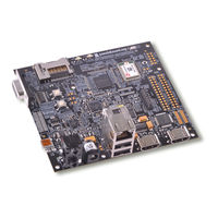
pandaboard OMAP4430 System Reference Manual (83 pages)
Brand:
pandaboard
| Category:
PCI Card
| Size: 10.53 MB
Table of Contents
Table of Contents
7
1 Introduction
11
OMAP4430 Pandaboard Overview
12
Table 1: Pandaboard Features
12
Overview of the OMAP4430 Pandaboard Kit Contents
13
2 OMAP4430 Pandaboard Architecture
14
Overview of the Pandaboard Architecture
14
Figure 1 - OMAP4430 Pandaboard Architectural Block Diagram
15
Figure 2 - OMAP4430 Pandaboard (Top View)
16
System Clock Distribution
17
OMAP4430 Processor
17
TWL6030 Power Companion IC
18
TWL6030 Core SMPS Outputs
18
TWL6030 V1V8 SMPS Output
19
TWL6030 V2V1 SMPS Output
19
TWL6030 VMEM SMPS Output
19
TWL6030 V1V29 SMPS Output
19
TWL6030 LDO Power Resources
19
TWL6030 Clock Circuitry
20
TWL6040 Audio Companion IC
20
SYSBOOT Configuration
21
Table 2: SYSBOOT[5:0] Definitions - Peripheral Preferred Booting
22
Table 3: SYSBOOT[5:0] Definitions - Memory Preferred Booting
23
Miscellaneous Power Circuitry
24
Input Power Circuitry
24
Figure 3 - SYSBOOT[5:0] Resistor Locations
24
Figure 4 - Pandaboard Input Power Circuitry Block Diagram
25
Usb/Ethernet Power Circuitry
26
Standard Volatile Memory
26
Debug UART Interface
26
SD/MMC Connector
27
Figure 5 - Panda UART3/RS-232 Block Diagram
27
HDMI Interface
28
Figure 6 - Panda SDMMC1 Card Cage Block Diagram
28
Figure 7 - Panda HDMI Interface Block Diagram
29
Display Interface
30
2.12.1 Parallel Display DVI-D Connector
30
Figure 8 - Panda Display Interface Block Diagram
30
Table 4: HDMI GPIO Definitions
30
Figure 9 - Panda DVI-D Output Block Diagram
31
2.12.2 Parallel Display Expansion Connector Interface
32
Table 5: DVI-D Display GPIO Definitions
32
Figure 10 - Panda Display Expansion Block Diagram
33
Table 6: LCD Expansion Connector "A" Pin Definitions (J1)
34
Figure 11 - Panda Display RMUX "A" Resistor Locations (Top Side of PCB)
35
Table 7: LCD Expansion Connector "B" Pin Definitions (J4)
35
Bluetooth/Wlan Interfaces
36
Figure 12 - Panda Display RMUX "B" Resistor Locations (Bottom Side of PCB)
36
Figure 13 - Pandaboard Wlan/Bluetooth Interface Block Diagram
37
Audio Interfaces
38
Table 8: Wlan/Bluetooth Module GPIO Definitions
38
USB Interfaces
39
2.15.1 USBOTG Interface
39
Figure 14 - Panda Audio Interface Block Diagram
39
2.15.2 USBB1 Phy Interface
40
Figure 15 - Panda USBOTG Interface Block Diagram
40
Figure 16 - Panda USBB1 Interface Block Diagram
41
Table 9: USB Host Port/Ethernet GPIO Definitions
41
Expansion Connectors (J3 & J6)
42
Figure 17 - Expansion Connector PCB Placement/Orientation
42
Table 10: Expansion Connector "A" Pin Definitions (J3)
43
Camera Expansion Connector (J17)
44
Table 11: Expansion Connector "B" Pin Definitions (J6)
44
Composite Video (J12)
45
Table 12: Camera Expansion Connector Pin Definitions (J17)
45
Figure 18 - Composite Video Connectivity
46
Figure 19 - Composite Video Connector J12 PCB Orientation
46
JTAG Connector (J8)
47
Figure 20 - 14-Pin JTAG Connector (J8)
47
LED Indicators
48
Table 13: JTAG Connector Pinout (J8)
48
User Interface Features
49
Figure 21 - Pandaboard LED Locations
49
2.21.1 S1 - Push Button Switch
50
2.21.2 S2 - Push Button Switch
50
C Device Mapping
50
Omap I C1
50
Omap I C2
50
Omap I C3
51
Omap I C4
51
Table 14: OMAP I
51
Table 15: OMAP I
51
Table 16: OMAP I
51
Table 17: OMAP I
51
3 Pandaboard S/W Interface
52
Readable Board Revision
52
Pandaboard Pin Multiplexing
52
Panda Base Platform Pin Multiplexing
52
Table 18: Board ID Read Values
52
Camera Expansion Connector Pin Multiplexing
56
Table 19: Pandaboard OMAP4430 Pin Multiplexing
56
Expansion Connector (J3 & J6) Pin Multiplexing
57
Table 20: Camera Expansion Connector (J17) Pin Multiplexing Options
57
Table 21: Expansion Connector (J3 & J6) Pin Multiplexing Options
58
OMAP4430 Pandaboard Key Components
59
OMAP4430 Pandaboard Key Component Datasheet Urls
60
Connector Datasheets
60
Table 22: OMAP4430 Pandaboard Key H/W Components
60
Key Electronic Component Datasheets
61
4 Test/Debug Information
62
Pandaboard Clock Signal Access
62
H_FREF_ALTCLK_IN_OMAP Probe Point
62
USBB1_PHY_REFCLK Probe Point
63
CLK32K_AUD Probe Point
63
Figure 22 - 38.4 Mhz Input Clock Probe Point (H_Fref_Altclk_In_Omap)
63
Figure 23 - USB Phy Ref Clock in Probe Point (USBB1_PHY_REFCLK)
63
Pandaboard Power Rail Signal Access
64
TWL6030 SMPS Output Probe Points
64
Figure 24 - 32Khz Audio Clock Probe Point (CLK32K_AUD)
64
VCXIO LDO Output Probe Point
65
Figure 25 - TWL6030 SMPS Output Probe Points
65
Pandaboard Interface Signal Access
66
TWL6040 PDM Interface Probe Points
66
Figure 26 - TWL6030 VCXIO LDO Output Probe Points
66
Pandaboard Schematic
67
Figure 27 - TWL6040 PDM Interface Probe Points
67
Pandaboard Bill of Materials
83
Pandaboard PCB Design Information
83
Advertisement
Advertisement
Related Products
pandaboard OMAP 4 Series
pandaboard OMAP4460 Pandaboard ES
pandaboard Categories
PCI Card
Motherboard
Single board computers
More pandaboard Manuals
Login
Sign In
OR
Sign in with Facebook
Sign in with Google
Upload manual
Upload from disk
Upload from URL