Sign In
Upload
Manuals
Brands
Motorola Manuals
Portable Radio
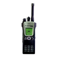
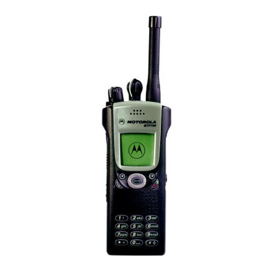
IMPRES Tetra MTP700
Motorola IMPRES Tetra MTP700 Radio Manuals
Manuals and User Guides for Motorola IMPRES Tetra MTP700 Radio. We have
4
Motorola IMPRES Tetra MTP700 Radio manuals available for free PDF download: Detailed Service Manual, Basic Service Manual, Basic User's Manual, Instruction Booklet
Motorola IMPRES Tetra MTP700 Detailed Service Manual (250 pages)
380 - 430 MHz 806 - 870 MHz
Brand:
Motorola
| Category:
Portable Radio
| Size: 6.11 MB
Table of Contents
Computer Software Copyrights
2
Trademarks
2
Chapter 2 Model Information & Accessories
3
Document History
3
Product Safety and RF Exposure for Portable Two-Way Radios
5
Fmrc Approved Equipment
8
Intrinsically Safe Radio Information
8
Operational Cautions
8
Operational Warnings
8
Repair of Fmrc Approved Products
9
Do Not Substitute Options or Accessories
10
Table of Contents
11
Appendix C Test Equipment
17
Related Publications
18
After Warranty Period
19
European Radio Support Centers (ERSC)
20
Asia Pacific Radio Support Centers
21
Piece Parts
21
Technical Support
21
Latin America Radio Support Centers
22
Warranty and Service Support
19
Warranty Period and Return Instructions
19
Model Information & Accessories
23
MTP700 Portable Radio Model Charts
23
Chapter 1 Scope & Warranty Information
17
Scope of this Manual
17
Manual Revisions
17
Appendix A Replacement Parts and Kits
24
MTP700 Portable Radio Model Information
27
MTP700 Portable Radio Model Specification
28
MTP700 Accessories-To-Model Chart
29
Chapter 3 Overview
31
General
31
Digital Modulation Technology
31
Overview
31
Chapter 4 Radio Information
33
Section Introduction
33
Block Diagram Overview
35
Receiver Section
37
Transmitter Section
37
Frequency Generating Section (Synthesizer)
38
Digital & Audio Section
38
General
35
TRANSCEIVER 400 Mhz
35
Block Diagrams Descriptions
39
Receiver Path
39
Transmitter Path
40
Frequency Generating Section
41
Digital & Audio Section
43
Receiver Path, Detailed Circuit Description
44
Transmitter Path, Detailed Circuit Description
47
Frequency Generating Section, Detailed Circuit Description
50
Digital & Audio Section, Detailed Circuit Description
52
Display and Keypad, Detailed Description
60
380-430 Mhz Board Layout, Schematics & Parts Lists
65
380-430 Mhz Main Board Top Side PCB No. 8466547A08
65
380-430 Mhz Main Board Bottom Side PCB No. 8466547A08
66
Digital and RF Block Diagram
67
DSP, Controller & Memory Schematic Diagram (Redcap2)
68
DSP, Controller & Memory Schematic Diagram (Memory)
69
GCAP (Audio & DC) Schematic Diagram - GCAP3
70
GCAP (Audio & DC) Schematic Diagram - Periphery
71
IO Interface & Connectors Schematic Diagram - 40 Pin Connector
72
Schematic Diagram - 16 Pin Connector
73
Switches & Associated Components Schematic Diagram - Switch
74
Switches & Associated Components Schematic Diagram - 24 Pin Connector
75
RF Section Block Diagram
76
RXU Schematic Diagram
77
RF Core Unit Schematic Diagram - WPIC
78
RF Core Unit Schematic Diagram - 2Nd
79
Main VCO Schematic Diagram
80
TXU Block Diagram
81
TXU-LNODCT Schematic Diagram
82
TXU-TX Power Amplifier Schematic Diagram
83
TXU-TX Front End Schematic Diagram
84
TXU-ESCORT/TX VCO Schematic Diagram
85
380-430 Mhz Radio Parts List
86
Test Procedures
93
Troubleshooting (400 Mhz)
93
General
93
Troubleshooting Flowcharts
93
Block Diagram Overview
123
Receiver Section
125
Transmitter Section
125
Frequency Generating Section
126
Digital & Audio Section
127
General
123
TRANSCEIVER 800 Mhz
123
Block Diagrams Description
128
Receiver Path
128
Transmitter Path
129
Frequency Generating Section
130
Digital & Audio Section
132
Detailed Circuit Description
133
Receiver Path, Detailed Circuit Description
133
Transmitter Path, Detailed Circuit Description
136
Frequency Generating Section, Detailed Circuit Description
139
Digital & Audio Section, Detailed Circuit Description
141
Display and Keypad, Detailed Description
149
806-870 Mhz Board Layout, Schematics & Parts Lists
155
806-870 Mhz Main Board Top Side PCB No. 8485951Z04
155
806-870 Mhz Main Board Bottom Side PCB No. 8485951Z04
156
Controller Memory Schematic Diagram (Redcap 2) Sheet 1
157
Controller Memory Schematic Diagram (Redcap 2) Sheet 2
158
DC Supply & Audio Schematic Diagram (GCAP 3) Sheet 1
159
DC Supply & Audio Schematic Diagram (GCAP 3) Sheet 2
160
I/O Interface Schematic Diagram Sheet 1
161
I/O Interface Schematic Diagram (Sheet 2
162
Switches and Associated Components Schematic Diagram (Sheet 1
163
Switches and Associated Components Schematic Diagram (Sheet 2
164
Receiver Front End Schematic Diagram
165
Receiver Back End Schematic Diagram
166
Transmitter Schematic Diagram (Sheet 1
167
Transmitter Schematic Diagram (Sheet 2
168
Frequency Generation Unit Schematic Diagram
169
ESCORT Schematic Diagram
170
Mhz Radio Parts List
171
Test Procedures
177
Troubleshooting (800 Mhz)
177
General
177
Troubleshooting Flowcharts
177
Chapter 5 Programming the Radio
207
Reading Codeplug
208
Programming Codeplug
208
Programming Frequency
209
Restoring Factory Frequencies of the Radio
210
Programming Firmware
210
Manual Mode Testing
211
Preparation for Testing
211
Tests
211
LCD Display Test
211
Chapter 6 Maintenance
213
Preventive Maintenance
213
Safe Handling of CMOS and LDMOS Devices
215
Disassembling and Reassembling the Radio - General
216
Repair Procedures and Techniques - General
216
Parts Replacement and Substitution
216
Radio Disassembly - Detailed
217
Front Cover from Chassis Disassembly
217
Chassis Assembly Disassembly
220
Radio Reassembly - Detailed
221
Chassis Assembly Reassembly
221
Chassis and Front Cover Reassembly
221
Service Aids
223
MTP700 Unit - Exploded View
224
Chapter 7 Keypad Board Layout, Schematics & Parts List
227
Keypad Board Top Side PCB No. 8466556A01
227
Keypad Board Bottom Side PCB No. 8466556A01
228
Keypad Board Schematic Diagram
229
Keypad Board Parts List
230
Chapter 8 Flex Layout, Schematics & Parts Lists
231
Interconnect Flex
231
Schematic for Interconnect Flex
232
Parts List for Interconnect Flex
232
Universal Connector Flex
233
Schematic for Universal Connector Flex
234
Parts List for Universal Connector Flex
234
Display Flex
235
Schematic for Display Flex
236
Parts List for Display Flex
236
Bottom Flex
237
Schematic for Bottom Flex
238
Parts List for Bottom Flex
238
Replacement Parts
239
Replacement Parts and Kits
239
Servicing MTP700 Portable Units
239
Service Kits
240
Appendix B Connector Pin Functions
243
Connector Pin Functions
243
General
243
Side Accessory Connector Pin Assignment
243
Bottom Accessory Connector Pin Assignment
245
Test Equipment
247
Appendix D Self Check (Error & Fail Codes)
249
General
249
Self Check Error Codes
249
Self Check (Error & Fail Codes
249
Before Using the Customer Programming Software (CPS)
207
Introduction
213
Advertisement
Motorola IMPRES Tetra MTP700 Basic User's Manual (60 pages)
TETRA Terminal
Brand:
Motorola
| Category:
Handhelds
| Size: 4.71 MB
Table of Contents
English
3
Table of Contents
3
Safety Information
5
Mtp700 Overview
6
Controls and Indicators
6
Audio Signal Tones
8
Key, Knob, and Button Overview
11
Mode Key
11
Soft Keys
11
Menu Key
11
On/Off-Volume Knob
11
Talkgroup Knob
11
The LED Status Indicator
12
Function Keys
12
Emergency Button
12
To Enter the Menu Options
13
To Exit the Menu Options
13
List of Menu Options
14
The Display
16
Display Icons
16
Displaying Long Numbers or Messages
17
Getting Started
18
Charging the Battery
18
Installing the Battery
18
Removing the Battery
19
Attaching the Antenna
19
Unlocking the MTP700
20
Powering on with Transmit Inhibit Active
20
Powering the MTP700 On/Off
20
Selecting TMO or DMO Operation
21
Entering TMO or DMO
21
Calls (Trunked Mode)
21
TMO Group Calls
21
Making a TMO Group Call
21
Receiving a TMO Group Call
22
Receiving a TMO Broadcast Call
22
Calls (Direct Mode)
22
DMO Group Calls
22
Exiting DMO
23
Receiving a DMO Group Call
23
Making a DMO Group Call
23
Calls (Private and Phone Calls)
24
Private Call
24
Making a Private Call
24
Receiving a Private Call
24
Phone and PABX Calls
25
Making a Phone or PABX Call
25
Emergency Mode
26
Entering or Exiting Emergency Mode (TMO & DMO)
26
Sending an Emergency Alarm (TMO Only)
26
Hot Microphone Feature
27
Making an Emergency Group Call
27
Quick Reference Guide
29
Ñîäåðæàíèå
31
Motorola Inc., 2005
32
Èíôîðìàöèÿ Ïî Òåõíèêå Áåçîïàñíîñòè
33
Îáçîð Ðàäèîñòàíöèè MTP700
34
Ñðåäñòâà Óïðàâëåíèÿ È Èíäèêàòîðû
34
Çâóêîâûå Òîíàëüíûå Ñèãíàëû
36
Êëàâèøà Ìåíþ
39
Êëàâèøà Ïåðåêëþ÷Åíèÿ Ðåæèìîâ
39
Êëàâèøà Ðàçãîâîðíîé Ãðóïïû
39
Îáçîð Êëàâèø, Ðó÷Åê È Êíîïîê
39
Ðó÷Êà Âêëþ÷Åíèÿ/Âûêëþ÷Åíèÿ Çâóêà
39
Ýêðàííûå Êëàâèøè
39
Êíîïêà Ýêñòðåííîãî Âûçîâà
40
Ñâåòîäèîäíûé Èíäèêàòîð Ñòàòóñà
40
Ôóíêöèîíàëüíûå Êëàâèøè
40
Âõîä Â Ïóíêò Ìåíþ
41
Âûõîä Èç Ïóíêòà Ìåíþ
41
Ñïèñîê Ïóíêòîâ Ìåíþ
42
Äèñïëåé
44
Èêîíêè Äèñïëåÿ
44
Îòîáðàæåíèå Äëèííûõ Íîìåðîâ Èëè Ñîîáùåíèé
45
Çàðÿäêà Àêêóìóëÿòîðà
46
Ïðåäâàðèòåëüíîå Îçíàêîìëåíèå
46
Óñòàíîâêà Àêêóìóëÿòîðà
46
Óäàëåíèå Àêêóìóëÿòîðà
47
Óñòàíîâêà Àíòåííû
47
Âêëþ÷Åíèå/Âûêëþ÷Åíèå Ïèòàíèÿ MTP700
48
Ïåðåäà÷È
48
Ðàçáëîêèðîâàíèå Ðàäèîñòàíöèè MTP700
48
DMO (Ïðÿìîé)
49
Âõîä Â Ðåæèì TMO (Òðàíêèíãîâûé) Èëè DMO (Ïðÿìîé)
49
Âûáîð Ðåæèìà TMO (Òðàíêèíãîâûé) Èëè
49
Âûçîâû (Òðàíêèíãîâûé Ðåæèì)
49
Âûïîëíåíèå Ãðóïïîâîãî Âûçîâà Â Ðåæèìå TMO
49
Ãðóïïîâûå Âûçîâû Â Ðåæèìå TMO
49
Âûçîâû (Ïðÿìîé Ðåæèì)
50
Ãðóïïîâûå Âûçîâû Â Ðåæèìå DMO
50
Ïðèåì Ãðóïïîâîãî Âûçîâà Â Ðåæèìå TMO
50
Ïðèåì Øèðîêîâåùàòåëüíîãî Âûçîâà Â Ðåæèìå TMO
50
Âûïîëíåíèå Ãðóïïîâîãî Âûçîâà Â Ðåæèìå DMO
51
Âûõîä Èç Ðåæèìà DMO
51
Ïðèåì Ãðóïïîâîãî Âûçîâà Â Ðåæèìå DMO
51
Âûçîâû (Èíäèâèäóàëüíûå È Òåëåôîííûå Âûçîâû)
52
Âûïîëíåíèå Èíäèâèäóàëüíîãî Âûçîâà
52
Èíäèâèäóàëüíûé Âûçîâ
52
Ïðèåì Èíäèâèäóàëüíîãî Âûçîâà
52
Âûïîëíåíèå Òåëåôîííîãî È ÀÒÑ-Âûçîâà
53
Òåëåôîííûå Âûçîâû È Âûçîâû Ó÷Ðåæäåí÷Åñêèõ ÀÒÑ
53
Âõîä Èëè Âûõîä Èç Ýêñòðåííîãî Ðåæèìà (TMO È DMO)
54
Ýêñòðåííûé Ðåæèì
54
Âûïîëíåíèå Ýêñòðåííîãî Ãðóïïîâîãî Âûçîâà
55
Ôóíêöèÿ Ãîðÿ÷Èé Ìèêðîôîí
55
Îñíîâíûå Ñâåäåíèÿ
57
Motorola IMPRES Tetra MTP700 Basic Service Manual (74 pages)
380 - 430 MHz/806 - 870 MHz
Brand:
Motorola
| Category:
Portable Radio
| Size: 2.53 MB
Table of Contents
Copyright
2
Trademarks
2
History
2
Computer Software Copyrights
2
Document History
3
Safety
5
Fmrc Approved Equipment
8
Intrinsically Safe Radio Information
8
Operational Cautions
8
Operational Warnings
8
Repair of Fmrc Approved Products
9
Do Not Substitute Options or Accessories
10
Table of Contents
11
Product Safety and RF Exposure for Portable Two-Way Radios
5
Chapter 1 Scope & Warranty Information
13
Scope of this Manual
13
Manual Revisions
13
Related Publications
13
Warranty and Service Support
14
European Radio Support Centers (ERSC)
15
Asia Pacific Radio Support Centers
16
Latin America Radio Support Centers
17
Chapter 2 Model Information & Accessories
19
MTP700 Portable Radio Model Charts
19
MTP750 Portable Radio Model Charts
23
MTP700/MTP750 Portable Radio Model Information
25
MTP700/MTP750 Portable Radio Model Specification
26
MTP700/MTP750 Accessories-To-Model Chart
27
Chapter 3 Overview
29
General
29
Digital Modulation Technology
29
Chapter 4 Programming the Radio
31
Before Using the Customer Programming Software (CPS)
31
Reading Codeplug
32
Programming Codeplug
32
Programming Frequency
33
Restoring Factory Frequencies of the Radio
34
Programming Firmware
34
Manual Mode Testing
35
Preparation for Testing
35
Tests
35
LCD Display Test
35
Chapter 5 Test Setup & Testing
37
Typical Test Setup
37
Test Equipment
38
Test Check List
39
How to Configure the IFR 2968 System Setup
41
How to Configure the IFR 2968 Manual Test Screen
43
RF Tests
44
Test Page
44
Receiver Tests
44
Transmitter Tests
46
Call Processing Test
46
Duplex Test (Phone/Private Mode)
47
DMO Test
49
IFR 2968 Test Setup
49
How to Configure the IFR 2968 Manual Test Screen
49
Radio Configuration for DMO
49
RF Test - Transmit Test
50
Service Flow Chart
51
Chapter 6 Maintenance
53
Introduction
53
Preventive Maintenance
53
Safe Handling of CMOS and LDMOS Devices
55
Repair Procedures and Techniques - General
56
Parts Replacement and Substitution
56
Disassembling and Reassembling the Radio - General
56
Radio Disassembly - Detailed
57
Front Cover from Chassis Disassembly
57
Chassis Assembly Disassembly
60
Radio Reassembly - Detailed
61
Chassis Assembly Reassembly
61
Chassis and Front Cover Reassembly
61
Service Aids
63
MTP700/MTP750 Unit - Exploded View
64
Appendix A Replacement Parts and Kits
67
Servicing MTP700/MTP750 Portable Units
67
Replacement Parts
67
Service Kits
68
Appendix B Connector Pin Functions
71
General
71
Side Accessory Connector Pin Assignment
71
Connector Pin Functions
71
Bottom Accessory Connector Pin Assignment
73
Advertisement
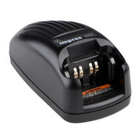
Motorola IMPRES Tetra MTP700 Instruction Booklet (4 pages)
impres Lite Single Charger for Tetra MTP700/MTP750
Brand:
Motorola
| Category:
Battery Charger
| Size: 0.21 MB
Advertisement
Related Products
Motorola MTP3100
Motorola IMPRES Tetra MTP750
Motorola MTP850
Motorola MTP6000 SERIES
Motorola MTP830 S
Motorola MTP8000Ex Series
Motorola MTP6550
Motorola TETRA MTP3550
Motorola MTX-800 Classic
Motorola MTH500
Motorola Categories
Cell Phone
Two-Way Radio
Baby Monitor
Cordless Telephone
Radio
More Motorola Manuals
Login
Sign In
OR
Sign in with Facebook
Sign in with Google
Upload manual
Upload from disk
Upload from URL