Sign In
Upload
Manuals
Brands
Mitsubishi Electric Manuals
Air Conditioner
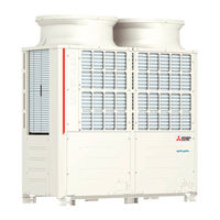
PQHY-P264TSHMU-A
Mitsubishi Electric PQHY-P264TSHMU-A Manuals
Manuals and User Guides for Mitsubishi Electric PQHY-P264TSHMU-A. We have
1
Mitsubishi Electric PQHY-P264TSHMU-A manual available for free PDF download: Service Handbook
Mitsubishi Electric PQHY-P264TSHMU-A Service Handbook (415 pages)
Brand:
Mitsubishi Electric
| Category:
Air Conditioner
| Size: 14.56 MB
Table of Contents
Safety Precautions
2
Precautions for Handling Units for Use with R410A
4
Before Installing the Unit
5
Before Installing the Unit and Performing Electrical Work
6
Before the Test Run
7
Table of Contents
8
1 I Read before Servicing
12
I Read before Servicing
12
Necessary Tools and Materials
13
Piping Materials
14
Storage of Piping
16
Pipe Processing
16
Brazing
17
Use of Oxidized Solder for Brazing
17
Use of Non-Oxidized Solder for Brazing
17
Air Tightness Test
18
Halide Torch
18
R22 Leakage Detector
18
Recommended Vacuum Gauge
19
Vacuum Drying (Evacuation)
19
Refrigerant Charging
21
Remedies to be Taken in Case of a Refrigerant Leak
21
Cylinder Color R410A Is Pink.
21
Refrigerant Charging in the Liquid State
21
Characteristics of the Conventional and the New Refrigerants
22
Notes on Refrigerating Machine Oil
23
Restrictions
24
2 II Restrictions
26
System Configuration
26
Types and Maximum Allowable Length of Cables
27
Terminal Block for Indoor-Heat Source Transmission Line
27
Terminal Block for Centralized Control
27
Switch Settings and Address Settings
28
Example of Wiring Connection
32
Sample System Connection
35
An Example of a System to Which an MA Remote Controller Is Connected
36
System with One Heat Source Unit
36
System with One Heat Source Unit to Which 2 or more LOSSNAY Connected
38
Group Operation of Units in a System with Multiple Heat Source Units
40
System Controller Connected to Transmission Line
42
System Controller Is Connected to Indoor-Heat Source Transmission Line
44
A System with Multiple BC Controller Connections
56
An Example of a System to Which an ME Remote Controller Is Connected
58
System Controller Connected to Centralized Control Transmission Line
60
An Example of a System to Which both MA Remote Controller and ME Remote Controller Are Connected
62
Restrictions on Pipe Length
67
System that Requires 16 BC Controller Ports or Fewer
71
System that Requires more than 16 BC Controller Ports
73
Difference between BC Controller and Indoor Units
74
Connecting the BC Controller
78
Heat Source Unit Components
82
3 III Heat Source Unit Components
84
Heat Source Unit Components and Refrigerant Circuit
84
Front View of a Heat Source Unit
84
Refrigerant Circuit
85
Control Box of the Heat Source Unit
87
Transformer Box
89
Heat Source Unit Circuit Board
90
M-NET Board
91
INV Board
92
Relay Board
94
Noise Filter
95
BC Controller Components
97
Control Box of the BC Controller
100
BC Controller Circuit Board
101
4 Remote Controller
104
Functions and Specifications of MA and ME Remote Controllers
106
Group Settings and Interlock Settings Via the ME Remote Controller
107
Remote Controller Function Selection Via the ME Remote Controller
109
Interlock Settings Via the MA Remote Controller
111
Using the Built-In Temperature Sensor on the Remote Controller
112
5 Electrical Wiring Diagram
114
Electrical Wiring Diagram of the Heat Source Unit
116
Electrical Wiring Diagram of the BC Controller
120
Electrical Wiring Diagram of Transmission Booster
129
6 Refrigerant Circuit
130
Refrigerant Circuit Diagram
132
Heat Source Unit
132
BC Controller
133
Principal Parts and Functions
135
Indoor Unit
138
7 Control
144
Functions and Factory Settings of the Dipswitches
146
Function of the Switch Indoor Unit
149
Function of the Switch Remote Controller
150
Switch Functions BC Controller
151
Controlling the Heat Source Unit
152
Bypass Control
153
Compressor Frequency Control
154
Refrigerant Recovery Controls
155
Capacity Control of Heat Exchanger
155
Heat Source Unit Heat Exchanger Capacity Control Patterns
156
Subcool Coil Control
158
Refrigerant Flow Control
158
Control at Initial Start-Up
158
Flowchart of Initial Operation
158
Emergency Operation Mode
161
Control Method
164
Cooling/Heating Circuit Control
165
General Function of System Equipment
165
Operation Mode
166
Demand Control
168
Controlling BC Controller
169
Operation Flow Chart
170
Mode Determination Flowchart
170
Operations in each Mode
172
Cooling Operation
172
Heating Operation
173
Dry Operation
174
8 Test Run Mode
182
Items to be Checked before a Test Run
184
Test Run Method
185
Operation Procedures
185
Operating Characteristic and Refrigerant Amount
186
Adjusting the Refrigerant Amount
186
Refrigerant Amount Adjust Mode
191
The Following Symptoms Are Normal
195
Standard Operation Data (Reference Data)
196
Troubleshooting
234
9 IX Troubleshooting
236
Error Code Lists
236
Responding to Error Display on the Remote Controller
239
Error Code 0403
239
Error Code 1102
240
Error Code 1301
241
Error Code 1302
242
Error Code 1500
243
Error Code 2000
244
Error Code 2134
245
Error Code 2135
246
Error Code 2500
247
Error Code 2502
249
Error Code 2503
251
Error Code 2600
252
Error Code 2601
252
Error Code 4102
253
Error Code 4106
255
Error Code 4115
256
Error Code 4116
257
Error Code 4220
258
Error Code 4230
262
Error Code 4240
263
Error Code 4250
264
Error Code 4260
267
Error Codes 5101, 5102, 5103, 5104
268
Error Codes 5102, 5103, 5104, 5105, 5106, 5107
269
Error Code 5110
270
Error Code 5201
271
Error Code 5301
272
Error Code 5701
274
Error Code 6201
274
Error Code 6202
274
Error Code 6600
275
Error Code 6601
275
Error Code 6602
276
Error Code 6603
277
Error Code 6606
277
Error Code 6607
278
Error Code 6608
287
Error Code 6831
288
Error Code 6832
289
Error Code 6833
290
Error Code 6834
291
Error Code 7100
292
Error Code 7101
293
Error Code 7102
294
Error Code 7105
295
Error Code 7107
296
Error Code 7110
297
Error Code 7113
298
Troubleshooting According to Remote Controller Malfunction
299
Flow Chart
302
Investigation of Transmission Wave Shape/Noise
312
Troubleshooting Principal Parts
315
High-Pressure Sensor
315
Low-Pressure Sensor
316
Solenoid Valve
317
Solenoid Valve Block
318
Judgment Methods and Possible Failure Mode
322
Heat Source Unit LEV Coil Removal Procedure
323
Replacement Procedure
325
Troubleshooting Principal Parts of BC Controller
326
Pressure Sensor
326
Temperature Sensor
328
Troubleshooting Flow Chart for LEV Solenoid Valve
330
Self-Diagnosis LED
332
Troubleshooting Flow Chart for Solenoid Valve Body
333
BC Controller Transformer
336
Inverter
337
Inverter Output Related Troubles
339
Trouble Treatment When the Main Power Breaker Is Tripped
340
Checking Procedure for Individual Components of Main Inverter Circuit
341
INV Board External Diagram
347
Control Circuit
348
Control Power Source Function Block
348
Troubleshooting Transmission Power Circuit of Heat Source Unit
349
Refrigerant Leak
352
Compressor Replacement Instructions
356
Water Heat Exchanger Assembly and Check Valve Replacement Instructions
358
Servicing the BC Controller
362
Service Panel
362
Control Box
362
Thermistor
363
Lev
364
Troubleshooting Using the Heat Source Unit LED Error Display
365
10 LED Monitor Display on the Heat Source Unit Board
366
How to Read the LED on the Service Monitor
368
LED Monitor Display
370
Current Data
370
Error History
381
Data on Indoor Unit System
388
Setting Data
395
Other Types of Data
412
Advertisement
Advertisement
Related Products
Mitsubishi Electric PQHY-P264TYSHMU-A
Mitsubishi Electric PQHY-P216TYSHMU-A
Mitsubishi Electric PQHY-P288TSHMU-A
Mitsubishi Electric PQHY-P288TYSHMU-A
Mitsubishi Electric PQHY-P200-900Y(S)LM-A
Mitsubishi Electric PQHY-P200YLM-A
Mitsubishi Electric PQHY-P250YLM-A
Mitsubishi Electric CITY MULTI PQHY-P250YEM-A
Mitsubishi Electric City Multi PQHY-P216ZSLMU-A1
Mitsubishi Electric City Multi PQHY-P240ZSLMU-A1
Mitsubishi Electric Categories
Air Conditioner
Controller
Projector
Inverter
Heat Pump
More Mitsubishi Electric Manuals
Login
Sign In
OR
Sign in with Facebook
Sign in with Google
Upload manual
Upload from disk
Upload from URL