Sign In
Upload
Manuals
Brands
Mitsubishi Electric Manuals
Controller
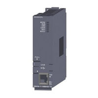
MELSEC Q24DHCCPU-VG
Mitsubishi Electric MELSEC Q24DHCCPU-VG Manuals
Manuals and User Guides for Mitsubishi Electric MELSEC Q24DHCCPU-VG. We have
1
Mitsubishi Electric MELSEC Q24DHCCPU-VG manual available for free PDF download: User Manual
Mitsubishi Electric MELSEC Q24DHCCPU-VG User Manual (516 pages)
Brand:
Mitsubishi Electric
| Category:
Controller
| Size: 11.83 MB
Table of Contents
Safety Precautions
3
Conditions of Use for the Product
11
Operating Precautions
12
Compliance with Emc and Low Voltage Directives
13
Introduction
13
Table of Contents
14
Related Manuals
22
Manual Page Organization
26
Terms
28
Discontinued Models
31
Packing List
31
Product Organization
31
Chapter 1 What Can be Done with C Controller Module
34
Q24Dhccpu-Ls
34
Q24Dhccpu-V
34
Q24Dhccpu-Vg
34
Q26Dhccpu-Ls
34
Chapter 1 What Can be Done with C Controller Module
35
Q12DCCPU-V (Extended Mode)
35
Features
36
Chapter 2 Part Names
37
Q24DHCCPU-V/-VG/-LS and Q26DHCCPU-LS
37
Q12Dccpu-V
43
Chapter 3 Specifications
46
General Specifications
46
Performance Specifications
47
Q24DHCCPU-V/-VG/-LS and Q26DHCCPU-LS
47
Q12Dccpu-V
50
Device Specifications
52
Device List
52
Device Description
53
Chapter 4 Software Packages
54
Chapter 5 Preparatory Procedure
55
Q24Dhccpu-V
55
Q24Dhccpu-Vg
57
Q24DHCCPU-LS and Q26DHCCPU-LS
59
Installation Procedure for Partner Operating System
61
Q12Dccpu-V
62
Chapter 6 Hardware Operations
64
Initialization
64
Q24DHCCPU-V/-VG/-LS and Q26DHCCPU-LS
65
Q12Dccpu-V
69
Change of Operation Status (RUN/STOP)
72
Reset
73
Restarting User CPU
75
Hardware Diagnostics
77
Q24DHCCPU-V/-VG/-LS and Q26DHCCPU-LS
77
Q12Dccpu-V
82
Chapter 7 System Configuration
88
Overall Configuration
88
Precautions for System Configuration
89
Basic Configuration (Single CPU System Configuration)
90
Main Base Unit/Power Supply Module
90
Extension Base Unit/Extension Cable
90
Battery
92
Multiple CPU System Configuration
93
Supported CPU Modules
93
Combination of CPU Modules
94
Mounting Position
95
CPU Number
97
I/O Module/Intelligent Function Module
98
Applicable Modules
98
Operating Precautions
101
Peripheral Configuration
104
SD Memory Card
105
Compactflash Card
106
Connection with USB Device
108
Connection with HMI (GOT)
111
Connection with Personal Computer
113
Connection with Other Peripherals (C Controller Module, Etc.)
116
Chapter 8 Installation and Wiring
118
Installation Environment and Installation Position
118
Installation and Removal of Module
118
Battery Installation
121
Inserting and Removing an SD Memory Card
122
Installing/Uninstalling and Unmounting a Compactflash Card
124
Inserting/Removing and Unmounting a USB Mass Storage Class Standard Compliant
126
Device
126
Cabling
127
USB Cabling
127
Ethernet Wiring
129
Analog RGB Output Cabling
133
RS-232 Cabling
134
Chapter 9 Maintenance and Inspection
136
Daily Inspection
136
Periodical Inspection
137
Battery Replacement Procedure
138
Standard ROM Life
139
Built-In SSD Life
139
Chapter 10 Function List
142
Part 3 Function
145
Chapter 11 Basic Functions
148
I/O Module and Intelligent Function Module Access Function
148
Switch Settings for I/O and Intelligent Function Modules
149
Interrupt from Intelligent Function Module and Interrupt Module
150
Input Response Time Selection (I/O Response Time)
152
Output (Y) Status Setting for Switching STOP to RUN
153
Error Time Output Mode Setting
154
Hardware Error Time CPU Operation Mode Setting
155
Self-Diagnostic Function
156
Watchdog Timer (WDT)
160
Clock Function
162
Remote Operation Function
165
Device Function
171
Refresh Function
172
Data Refresh Function
173
Link Refresh Function
177
Link Refresh Cycle Setting
177
Security Function
178
Access Authority Setting Function
179
Individual Identification Function
181
File Access Restriction Function
185
Service Setting Function
187
Event History Collection Function
189
Analog RGB Port Display Function
190
Battery Less Drive
192
Chapter 12 Functions Accessed Via Ethernet Ports
194
User Ethernet Port (Q24DHCCPU-V/-VG/-LS and Q26DHCCPU-LS)
194
Built-In Ethernet Port (Q12DCCPU-V) Function
194
Telnet Function
196
FTP Function
199
Time Setting Function (SNTP)
201
System Ethernet Port (Q24DHCCPU-V/-VG/-LS and Q26DHCCPU-LS)
202
Built-In Ethernet Port (Q12DCCPU-V) Function
202
Time Setting Function (SNTP)
204
SLMP (MC Protocol) Communication
206
Chapter 13 Functions Accessed Via a Network Module
210
Overview of Data Communication Via Network
211
Cyclic Transmission
211
Access by Link Refresh Function
214
Direct Access
219
Buffer Memory Access
221
Transient Transmission
223
Message Communication
223
Other Station Device Access
225
Each Network Module Access Function
227
CC-Link IE Controller Network Module
227
MELSECNET/H Module
232
CC-Link IE Field Network Master/Local Module
234
CC-Link Module
239
Processing Times
246
Link Refresh Time
246
Delay Time in Cyclic Transmission
247
Reducing the Link Refresh Time
251
Chapter 14 Functions Used by Multiple Cpu System
253
Data Communications Using CPU Shared Memory
253
CPU Shared Memory Structure
254
Data Communications Using Auto Refresh
258
Communication Using the Multiple CPU High Speed Transmission Area and Auto Refresh
263
Data Communications Without Using Auto Refresh
268
Interrupt from Another CPU
276
Interrupt from C Controller Module
277
Interrupt from Controller CPU
278
Precautions
281
Multiple CPU Synchronous Interrupt Function
281
Issuing an Interrupt to Another CPU
282
Function to Access to Devices of Other CPU Modules
283
Access to Programmable Controller CPU and C Controller Module
283
Access to Motion CPU
284
Remote Control Function of Other CPU Modules
285
Sequence Program Control Function
286
Motion CPU Control Instruction
287
Multiple CPU Synchronized Boot-Up
288
Chapter 15 Parameter
290
Parameter List
291
CCPU Parameter Settings
291
Network Parameter Settings
293
Multiple CPU System Parameter Settings
296
Parameters Required for Multiple CPU System
296
Multiple CPU Parameter Importing
297
Parameter Number
298
Chapter 16 I/O Number Assignment
300
I/O Number Assignment
300
Assignment Order
300
I/O Number of each Slot
301
I/O Number of each CPU Module
301
Chapter 16 I/O Number Assignment
301
Start Point of the I/O Numbers (00H)
302
Setting I/O Numbers
303
Base Unit Assignment Setting
305
Chapter 17 Execution Order and Operation Processing of C Controller Module
306
Execution Order
306
Operation Processing
307
Initial Processing
307
I/O Access Timing
308
RUN, STOP and PAUSE Status Operation Processing
309
Operation Processing During Momentary Power Failure
310
Controller Module
310
Chapter 18 Memories and Files
311
Memories and Files of Q24DHCCPU-V
311
Memory Type
311
Storable Data
315
Drive Name Assignment and Format
316
Files
318
Memories and Files of Q24DHCCPU-VG
320
Memory Type
320
Storable Data
324
Drive Name Assignment and Format
325
Files
327
Memories of Q24DHCCPU-LS and Q26DHCCPU-LS
329
Memory Type
329
Memories and Files of Q12DCCPU-V
331
Memory Type
331
Storable Data
333
Drive Name Assignment and Format
334
Files
336
Chapter 19 Programming
338
Development Environment
338
Chapter 19 Programming
339
Dedicated Function Library
339
Programming Procedure
339
Precautions for Programming
341
Precautions for Program Creation
341
Precautions for Interrupt Service Routine (ISR)
343
Precautions for CW Workbench Connection
344
Vxworks Image File Check
345
Creating a Script File
346
User Program Registration
350
Q24Dhccpu-V/-Vg
350
Q12Dccpu-V
352
Chapter 20 Programming of C Controller Module Dedicated Function
355
Outline of Functions
355
Function List
355
Programming Flow
357
Precautions
357
Chapter 21 Programming Using Bus Interface Functions
358
Function List
358
Outline of Functions
358
Chapter 21 Programming Using Bus Interface Functions
359
Precautions
362
Programming Flow
362
Chapter 22 Programming Using Melsec Data Link Functions
364
Function List
364
Outline of Functions
364
Chapter 22 Programming Using Melsec Data Link Functions
365
Programming Flow
365
Precautions
366
Accessible Networks and Devices
368
Access Via a Bus
369
Access Via CC-Link IE Controller Network
372
Access Via MELSECNET/H
377
Access Via CC-Link IE Field Network
383
Access Via CC-Link
389
Part 5 Troubleshooting
395
Chapter 23 Troubleshooting
396
LED Lighting State
397
The POWER LED on the Power Supply Module
397
The LIFE LED on the Life Detection Power Supply Module
398
POWER LED of Redundant Power Supply Module Is Lit Red
399
When MODE LED of the C Controller Module Is Not Lit
399
C Controller Module ERR.LED Is Lit or Flashing
399
C Controller Module RUN LED Is Kept Flashing
400
C Controller Module U RDY LED Is Not Lit
400
Output Module LED Is Not Lit
400
Display State
401
Nothing Is Displayed on the General-Purpose Analog RGB Display
401
Checking the Error Details
402
Checking for Functional Errors
402
Setting/Monitoring Tools for the C Controller Module Cannot be USB-Connected
403
Ethernet Communication with the C Controller Module Cannot be Established
404
Parameter Reading/Writing Fails
406
File Access Fails
407
Communication with Peripherals Fails
407
USB Device Cannot be Recognized
408
File Read-Out (Download) from C Controller Module Fails
408
An Error Occurs During User Program Execution
408
The User Program Does Not Start
409
Event History Data Are Incorrect
410
Refresh Function (Data Refresh, Link Refresh) and Data Link of Network Are Stopped
410
Partner Application Does Not Operate
410
Appendices
411
Appendix 1 Error Code List
411
Appendix 1.1 CPU Error Code
411
Appendix 1.2 Error Code Detected During Device Monitor Execution
422
Appendix 1.2
422
Error Code During Function Execution
423
Appendix 1.3 Error Code During Function Execution
434
Appendix 1.4 Error Code Returned to Peripherals
434
Appendix 1.5 Error Code for SLMP (MC Protocol) Communication
435
Appendix 2 Event Number List
436
Appendix 3 Vxworks Component List
442
Appendix 3
442
Q24Dhccpu-V
442
Appendix 3.2
451
Q12Dccpu-V
460
Appendix 3.2 Q24DHCCPU-VG
451
Appendix 4 Replacement of Q12DCCPU-V
467
Appendix 4.1 Replacement Q12DCCPU-V (Basic Mode) with Q24DHCCPU-V/-VG
467
Appendix 4.2 Replacement Q12DCCPU-V (Basic Mode) with Q12DCCPU-V
467
(Extended Mode)
472
Appendix 5 Function Processing Time
477
Appendix 6 List of Special Relays
480
Appendix 7 List of Special Registers
482
Appendix 8 Battery Life
489
Appendix 9 Checking Serial Number and Function Version
490
Appendix 10 Added or Changed Functions
492
Appendix 10.1 C Controller Module Upgrade
492
Appendix 10
492
Q24Dhccpu-V
492
Appendix 10.1.2 Q24DHCCPU-VG
493
Appendix 10.1.2
493
Q12Dccpu-V
494
Appendix 11 Fail-Safe Circuit
495
Appendix 12 Calculating Heat Generation of Programmable Controller
501
Appendix 13 External Dimensions
501
Appendix 14 BIOS Setup
504
Index
506
Revisions
509
Warranty
513
Trademarks
514
Advertisement
Advertisement
Related Products
Mitsubishi Electric MELSEC Q24DHCCPU-V
Mitsubishi Electric MELSEC Q24DHCCPU-LS
Mitsubishi Electric melsec q20ud(e)hcpu
Mitsubishi Electric melsec q26ud(e)hcpu
Mitsubishi Electric Q26UDVCPU
Mitsubishi Electric Q25HCPU
Mitsubishi Electric Q25PHCPU
Mitsubishi Electric Q25PRHCPU
Mitsubishi Electric MELSEC Q26DHCCPU-LS
Mitsubishi Electric QX81
Mitsubishi Electric Categories
Air Conditioner
Controller
Projector
Inverter
Heat Pump
More Mitsubishi Electric Manuals
Login
Sign In
OR
Sign in with Facebook
Sign in with Google
Upload manual
Upload from disk
Upload from URL