Sign In
Upload
Manuals
Brands
Mitsubishi Electric Manuals
Controller
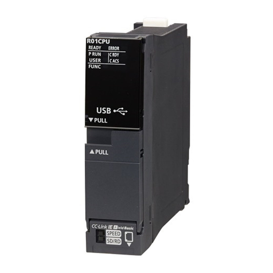
MELSEC iQ-R-R00CPU
Mitsubishi Electric MELSEC iQ-R-R00CPU Manuals
Manuals and User Guides for Mitsubishi Electric MELSEC iQ-R-R00CPU. We have
1
Mitsubishi Electric MELSEC iQ-R-R00CPU manual available for free PDF download: User Manual
Mitsubishi Electric MELSEC iQ-R-R00CPU User Manual (1028 pages)
MELSEC iQ-R series CPU Module Application User's Manual
Brand:
Mitsubishi Electric
| Category:
Controller
| Size: 31 MB
Table of Contents
Safety Precautions
3
Conditions of Use for the Product
16
Introduction
18
Table of Contents
19
Relevant Manuals
35
Terms
36
Part 1 Cpu Module Operation
39
Chapter 1 Running a Program
40
Scan Configuration
40
Initial Processing (When Powered on or Switched to RUN)
40
I/O Refresh
41
Program Operation
41
END Processing
41
Scan Time
42
Initial Scan Time
42
Constant Scan
43
Device/Label Access Service Processing Setting
45
Data Communication and I/O Processing
49
Data Communication
49
I/O Processing and Response Delay
49
Refresh Mode
50
Direct Mode
52
Program Flow
54
Program Execution Type
55
Initial Execution Type Program
55
Scan Execution Type Program
56
Fixed Scan Execution Type Program
56
Event Execution Type Program
61
Standby Type Program
65
Execution Type Change
66
Group Setting for Refresh
67
Subroutine Program
68
Interrupt Program
69
Interrupt Period Setting
79
Interrupt Enabled During Instruction Execution
79
Processing at Interrupt Program Startup
80
Multiple Interrupt Function
83
Chapter 2 Cpu Module Operation Processing
89
Operation Processing by Operating Status
89
Operation Processing When Operating Status Is Changed
90
Output Mode at Operating Status Change (STOP to RUN)
91
Operation Processing at Momentary Power Failure
93
Chapter 3 Memory Configuration of the Cpu Module
94
Memory Configuration
94
Program Memory/Program Cache Memory
95
Device/Label Memory
96
Data Memory
100
Function Memory
100
Refresh Memory
100
CPU Buffer Memory
100
Signal Flow Memory
101
SD Memory Card
101
File Size Unit in Memory
102
Memory Operation
103
Initialization and Value Clear
103
Files
104
File Types and Storage Memory
104
File Operation Available
106
File Size
107
Part 2 Functions
109
Chapter 4 Clock Function
110
Time Setting
110
Clock Data
110
Changing the Clock Data
110
Reading the Clock Data
111
Precautions on the Clock Data
111
Setting Time Zone
112
Daylight Saving Time Function
113
Daylight Saving Time Setting
113
Timing of Daylight Saving Time Adjustment
114
Daylight Saving Time Function Operation Check
115
Operation of Other Functions Using Clock Data During Daylight Saving Time
115
Precautions
115
System Clock
116
Special Relay Used for System Clock
116
Special Register Used for System Clock
116
Chapter 5 Writing Data to the Cpu Module
117
Writing Data to the Programmable Controller
117
Online Change
117
Online Change (Ladder Block)
117
File Batch Online Change
121
Precautions
122
Chapter 6 Ras Functions
127
Scan Monitoring Function
127
Scan Time Monitoring Time Setting
127
Watchdog Timer Reset
127
Precautions
128
Self-Diagnostics Function
129
Self-Diagnostics Timing
129
Check Method of Error
129
CPU Module Operation Upon Error Detection Setting
130
Error Detection Invalidation Setting
134
Error Clear
135
Event History Function
138
Event History Setting
138
Logging of the Event History
139
Viewing the Event History
141
Clearing the Event History
141
Precautions
142
Program Cache Memory Auto Recovery Function
142
Chapter 7 Remote Operation
143
Remote RUN/STOP
143
Executing Method
143
Precautions
144
Remote PAUSE
144
Executing Method
144
Setting RUN-PAUSE Contacts
145
Remote RESET
145
Enabling Remote RESET
145
Executing Method
145
Chapter 8 Boot Operation
146
Boot Operation Procedure
146
Specifiable File Types
147
Allowed Maximum Number of Boot Files
147
Configuring the Boot Setting
148
Operation When Security Functions Are Enabled
149
When a Security Key Is Set
149
When a File Password Is Set
149
Precautions
149
Chapter 9 Monitor Function
150
Real-Time Monitor Function
150
Chapter 10 Test Function
152
External Input/Output Forced On/Off Function
152
Device Test with Execution Conditions
159
Chapter 11 Data Logging Function
172
Data to be Collected
173
Number of Data Points
173
Data Type
173
Data Collection Conditions
175
Each Scan
175
Time Specification
175
Interrupt Occurrence
176
Condition Specification
177
Logging Type
180
Operating Procedure for Continuous Logging
180
Operating Procedure for Trigger Logging
181
Data Logging File
185
Storage Format of Data Logging Files
185
Storage Location of Data Logging Files
185
States of the Data Logging Function
186
Data Logging States
186
LED Status
187
Steps until the Collected Data Is Saved
188
Internal Buffer
190
Switching to a Storage File
192
Missing Data
195
Conditions under Which Missing Data Occurs
195
Data Logging File Transfer (Auto Transfer to FTP Server)
196
Data Logging File Transfer to Data Memory
204
Setting Behavior at the Time of Transition to RUN
205
Auto Logging
206
SD Memory Card Replacement
208
SD Memory Card Life When the Data Logging Function Is Used
209
Errors Generated During Data Logging
210
Special Relay and Special Register Used by the Data Logging Function
210
Precautions to Take When Using the Data Logging Function
211
Chapter 12 Debug Function
223
Memory Dump Function
223
Object Data
224
Trigger Condition
224
Procedure for Memory Dump
226
Flow of Data Collection
227
Memory Dump File
228
States of the Memory Dump Function
229
Sizes of Files Used for the Memory Dump Function
230
Special Relay and Special Register Used in the Memory Dump Function
231
Precautions for the Memory Dump Function
231
Chapter 13 Database Function
234
Specifications
235
Database Access Instruction
238
Usage Procedure
238
Creating Unicode Text Files
239
Transactions for Databases
242
Folder Configuration of Databases
242
Timing of Database Update
243
Precautions
243
CPU Module Database Access (from External Device) Function
244
Usage Procedure
244
Built-In Database Access Setting
246
Creating a Database
247
Adding a Database to the ODBC Data Source
248
Application Example
250
Precautions
261
Chapter 14 Pid Control/Process Control Function
264
PID Control Function
264
Process Control Function
265
Process Control by Using Process Control Function Blocks
265
Process Control by Using Process Control Instructions
266
Chapter 15 Cpu Module Data Backup/Restoration Function
267
Backup Function
272
Backup Processing Triggered by Turning on SM1351
274
Automatic Backup Using SD944
275
Checking Backup Errors
277
Precautions
277
Restoration Function
281
Restoration Processing Triggered by Turning on SM1354
283
Automatic Restoration Using SD955
284
Checking Restoration Errors
284
Precautions
285
Chapter 16 Multiple Cpu System Function
290
Out-Of-Group I/O Fetch
291
Accessing Controlled Module
291
Accessing Non-Controlled Module
291
Operation Settings
293
Stop Setting
293
Synchronous Startup Setting
294
Clock Data
297
Multiple CPU Parameter Checking
298
Data Communication between CPU Modules
299
Memory to be Used
299
Fixed Scan Communication Setting
304
Error Detection Setting
304
Module-By-Module Data Guarantee
305
Communication through Refresh
307
Communication through Direct Access
311
Data Guarantee by Program
314
Communication between CPU Modules in Error State
317
Multiple CPU Synchronous Interrupt
318
Execution Timing
319
Multiple Interrupt
319
Precautions
319
Chapter 17 Security Function
320
Chapter 18 Sequence Scan Synchronization Sampling Function
322
Chapter 19 Label Initialization Function
324
Initialization of Labels after Rebuilt All (Reassignment)
324
Label Initial Value Reflection Setting
326
Chapter 20 Routing Setting
328
Setting Method
328
Setting Example
329
Precautions
329
Part 3 Devices, Labels, and Constants
331
Chapter 21 Devices
332
Device List
332
Device Setting
333
Range of Use of Device Points
334
User Device
335
Input (X)
335
Output (Y)
335
Internal Relay (M)
336
Latch Relay (L)
336
Link Relay (B)
336
Annunciator (F)
336
Link Special Relay (SB)
338
Edge Relay (V)
339
Step Relay (S)
339
Timer
340
Counter
346
Data Register (D)
349
Link Register (W)
349
Link Special Register (SW)
349
System Device
350
Function Device (FX/FY/FD)
350
Special Relay (SM)
351
Special Register (SD)
351
Link Direct Device
351
Specification Method
351
Specification Range
352
Difference from Link Refresh
352
Module Access Device
353
Precautions
354
CPU Buffer Memory Access Device
354
Specification Method
354
Index Register (Z/LZ)
355
16-Bit Index Modification
355
Device for Which Index Modification Can be Performed
356
Index Register Setting
356
Combination of Index Modification
357
Precautions
357
File Register (R/ZR)
359
Specification Method
359
Setting File Registers
360
Clearing File Registers
361
Refresh Data Register (RD)
361
Refresh Memory Setting
361
Nesting (N)
362
Pointer (P)
363
Global Pointer
363
Local Pointer
364
Pointer Setting
365
Interrupt Pointer (I)
365
Interrupt Factors of the Interrupt Pointer Numbers
366
The Priority for the Interrupt Pointer Numbers and Interrupt Factors
366
Network No. Specification Device (J)
367
I/O No. Specification Device (U)
367
SFC Block Device (BL)
367
SFC Transition Device (TR)
367
Global Device
368
Local Device
368
Indirect Specification
373
Chapter 22 Labels
374
Global Labels
374
Local Labels
374
Classes
375
Data Types
376
Arrays
379
Structures
383
Label Access Setting from External Device
385
Configuration Procedure
386
Label Communication Data Storage Location and Operation at the Time of each Setting Operation
386
File Operation
386
Precautions
387
Chapter 23 Latch Function
389
Latch with Battery
389
Types of Latch
389
Applicable Devices and Labels
390
Setting Latch on Devices
391
Setting Latch on Labels
395
Clearing Latch Range Data
395
Precautions
395
Latch with Battery-Less Option Cassette
396
Usage Procedure
396
Precautions
398
Chapter 24 Device/Label Initial Value Settings
399
Setting Initial Device/Label Values
400
Setting Initial Device Values
400
Setting Initial Label Values
401
Applicable Devices/Labels
402
Precautions
402
Chapter 25 Constants
403
Decimal Constant (K)
403
Hexadecimal Constant (H)
403
Real Constant (E)
404
Setting Range for Real Numbers
404
Processing When Operation Is in Progress
404
Character String Constant
404
Notation of Constants
405
Part 4 When Using the Process Cpu (Redundant Mode)
407
Chapter 26 Basic Concept
408
System
408
System Switching between the Control System and Standby System
409
System Consistency Check
409
Operation Mode of the Process CPU
409
Operation Modes of the Redundant System
410
Scan Configuration
411
Determination of Control System/Standby System
412
When Starting up both Systems Simultaneously
412
When Starting up One System First
413
When One System Is Started Automatically Even Though a Tracking Communication Error Has Occurred
415
When Starting up the Previous Control System as the Control System
420
State Transition of the Redundant System
422
Chapter 27 Procedure for Starting up a Redundant System
424
Overview
424
Starting up both Systems at a Time
424
Starting up the Systems One by One
426
Precautions on Starting up the System When the Data Logging Function Is Used
429
Wiring
430
Wiring the Redundant Function Modules
430
Wiring to the Power Supply Modules in a Redundant System
431
Creating a Project
432
Connecting a Personal Computer and a CPU Module
432
System A/B Settings
433
Writing Data to the Programmable Controller
435
Monitoring the Program
436
Chapter 28 Functions
437
Operation Mode Change
440
Switching Procedure
440
Precautions
442
System Switching
443
System Switching Method
443
Operation at System Switching
448
Execution Availability of System Switching
449
Check Method of System Switching Information
451
Precautions
453
Tracking Transfer
456
Tracking Data
457
Tracking Block and Tracking Trigger
460
Setting Procedure for Tracking Transfer
461
Tracking Transfer Setting
462
Tracking Mode
466
Precautions
469
Memory Copy from Control System to Standby System
470
Automatic Memory Copy
472
Memory Copy with the Engineering Tool
473
Memory Copy with the Special Relay and Special Register
474
Precautions
476
System Consistency Check
477
File
479
Operating Status
480
Mounting Status of Main Base Unit
480
SD Memory Card
480
Program Execution in both Systems
481
Operation of a Program Executed in both Systems
483
Precautions
485
Redundant System Operation Setting
487
Standby System Output Setting
488
Redundant Function Module Communication Test
489
Execution Procedure of the Module Communication Test
489
Constant Scan
490
Online Change
491
RAS Function
492
Clearing Errors on the Standby System CPU Module from the Control System CPU Module
492
Remote Operation
493
Remote RUN, Remote STOP, Remote PAUSE
493
Remote RESET
494
Precautions
494
Boot Operation
495
External Input/Output Forced On/Off Function
496
Data Logging Function
500
Data Logging States
500
LED Status
501
Data Collection Conditions
501
Trigger Logging
501
Switching to a Storage File
502
Writing the Data Logging Setting
502
Auto Logging Function
502
SLMP Communication
503
Chapter 29 Precautions on Programming
504
Instructions Not Available in Redundant System
504
Instructions that Cause Stop Errors
504
Instructions that Need to be Executed Again in a New Control System
505
Instructions Whose Operations Vary Depending on Tracking of the Signal Flow Memory
508
Instructions that Affect the Status of Another Instruction When Executed
510
Instruction that Causes Different Operation Results between the Control System and Standby System
510
Precautions for Using the COM or ZCOM Instruction
511
Precautions for Using the ADRSET Instruction
511
Interrupt from Modules
512
System Switching in Backup Mode
512
System Switching in Separate Mode
512
When the Operation Mode Is Switched to the Separate Mode
512
When the Operation Mode Is Switched to the Backup Mode
513
Precautions for Using the Annunciator (F)
513
Precautions on Timers and Timer Function Blocks
514
Precautions on Access to Intelligent Function Module or External Devices
515
Precautions on Writing Data from GOT or External Devices
517
Precautions on Outputting in the Middle of the Scan
517
Chapter 30 Maintenance and Inspection for a Redundant System
518
Module Replacement in the Redundant System
518
Replacing a CPU Module
519
Replacing a Power Supply Module
521
Replacing a Redundant Power Supply Module
521
Replacing a Redundant Function Module
522
Replacing I/O Modules
522
Replacing a Network Module
523
Replacing a Main Base Unit
523
Part 5 When Using the Safety Cpu
525
Chapter 31 Running a Safety Program
526
Overview
526
Safety Program
527
Safety Cycle Time
529
Setting Method
529
Safety CPU Operating Status
530
Operation Processing Based on Safety CPU Operating Status
530
Operation Processing When Operating Status of the Safety CPU Changes
530
Chapter 32 Memory Specifications
531
Memory Configuration
531
Device/Label Memory
531
File Size Unit in Memory
532
Memory Operation
532
Files
533
File Types and Storage Memory
533
File Operation Available
534
File Size
536
Chapter 33 Functions
537
Safety Operation Mode
539
Checking the Safety Operation Mode
539
Switching the Safety Operation Mode
540
Operations Restricted in SAFETY MODE
542
Continuous RUN Prevention in TEST MODE
543
Measuring the Continuous RUN Time in TEST MODE
543
Setting Method
543
Checking the Continuous RUN Time in TEST MODE
543
Safety Diagnostic Function
544
Safety Data Identify Check
545
Safety Communication Function
545
Device/Label Memory Area Setting
546
Default Capacity
546
Setting Range of Capacity of each Area
547
Setting Method
549
Data Logging Function
551
Data to be Collected
551
Data Collection Conditions
551
Trigger Conditions
551
Output Settings
551
Auto Logging
551
RAS Functions
552
Self-Diagnostic Function
552
Error Clear
553
Chapter 34 Safety Devices, Safety Labels, and Constants
556
Safety Devices
556
List of Safety Devices
556
Safety User Devices
557
Safety System Devices
559
Safety Global Devices
560
Safety Local Devices
560
Safety Label
561
Safety Label Types
561
Classes
563
Data Types
564
Structures
564
Constants
564
Chapter 35 Basic Concept
566
System
567
System Switching between the Control System and Standby System
567
System Consistency Check
567
Operation Mode of the SIL2 Process CPU
568
Operation Modes of the System
568
Safety Operation Mode
568
Checking the Safety Operation Mode
568
Operations Restricted in SAFETY MODE
569
Scan Configuration
570
Determination of Control System/Standby System
571
When Starting up both Systems Simultaneously
571
When Starting up One System First
572
When One System Is Started Automatically Even Though a Tracking Communication Error Has Occurred
574
When Starting up the Previous Control System as the Control System
579
35.9 State Transition of a System Using the SIL2 Process CPU
580
Running a Safety Program
581
Overview
581
Safety Program
582
Safety Cycle Time
584
SIL2 Process CPU Operating Status
585
Memory Specifications
586
Memory Configuration
586
File Size Unit in Memory
587
Memory Operation
587
Files
588
Process Cpu
592
Chapter 36 Procedure for Starting up a System Using the Sil2
592
Overview
592
Wiring
599
Wiring the Redundant Function Modules
599
Wiring to the Power Supply Modules in a System Using the SIL2 Process CPU
600
Creating a Project
601
Connecting a Personal Computer and a CPU Module
602
System A/B Settings
603
Writing Data to the Programmable Controller
605
Monitoring the Program
606
Chapter 37 Functions
607
System Switching
611
System Switching Method
611
Operation at System Switching
616
Execution Availability of System Switching
618
Check Method of System Switching Information
619
Precautions
621
Tracking Transfer
624
Tracking Data
625
Tracking Block and Tracking Trigger
628
Setting Procedure for Tracking Transfer
629
Tracking Transfer Setting
630
Safety Tracking Transfer Setting
633
Tracking Mode
634
Precautions
637
Memory Copy from Control System to Standby System
639
Memory Copy with the Engineering Tool
642
Precautions
643
System Consistency Check
644
File
646
Operating Status
647
Mounting Status of Main Base Unit
647
SD Memory Card
648
Safety Operation Mode
648
Program Execution in both Systems
649
Operation of a Program Executed in both Systems
650
Precautions
652
Redundant System Operation Setting
654
Standby System Output Setting
655
Redundant Function Module Communication Test
656
Execution Procedure of the Module Communication Test
656
Switching Safety Operation Mode
657
Safety Diagnostic Function
660
Safety Data Identify Check
660
Safety Communication Function
661
Safety I/O Hold Time
662
Online Change
664
Constant Scan
664
Remote Operation
665
Remote Run/Remote Stop/Remote PAUSE
665
Remote RESET
666
Precautions
666
Device/Label Memory Area Setting
667
Default Capacity
667
Setting Range of Capacity of each Area
667
Setting Method
669
RAS Functions
671
Self-Diagnostic Function
671
Error Clear
673
Clearing Errors on the Standby System CPU Module from the Control System CPU Module
675
SLMP Communications
676
Chapter 38 Safety Devices, Safety Labels, and Constants
677
Safety Devices
677
List of Safety Devices
677
Safety User Devices
678
Safety System Devices
681
Safety Global Devices
682
Safety Local Devices
682
Safety Label
683
Safety Label Types
683
Classes
685
Data Types
686
Structures
686
Constants
686
Chapter 39 Precautions on Programming
687
39.1 Instructions Not Available in System Using SIL2 Process CPU
687
Instructions that Need to be Executed Again in a New Control System
687
Instructions Whose Operations Vary Depending on Tracking of the Signal Flow Memory
690
Instructions that Affect the Status of Another Instruction When Executed
692
Instructions that Cause Different Operation Results between the Control System and Standby System
692
Precautions for Using the COM or ZCOM Instruction
693
Precautions for Using the ADRSET Instruction
693
Interrupt from Modules
694
Precautions for Using the Annunciator (F)
694
Precautions on Timers and Timer Function Blocks
695
Precautions on Access to Intelligent Function Module or External Devices
696
Precautions on Writing Data from GOT or External Devices
698
Precautions on Outputting in the Middle of the Scan
698
Process Cpu
699
Chapter 40 Maintenance and Inspection for a System Using Sil2 Process Cpu
699
Replacing a CPU Module and SIL2 Function Module
700
Replacing a Power Supply Module
700
Replacing a Redundant Power Supply Module
701
Replacing a Redundant Function Module
701
Replacing a Network Module
701
Replacing a Main Base Unit
702
40.1 Module Replacement in a System Using the SIL2 Process CPU
699
Appendices
703
Appendix 1 Error Codes
703
Error Code System
703
Operation When an Error Occurs
705
Safety Output Operation When Error Occurs
705
How to Clear Errors
705
List of Error Codes
705
Appendix 2 Event List
790
How to Read the Event List
790
Event List
792
Appendix 3 Troubleshooting by Symptom
800
When the POWER LED of the Power Supply Module Turns off
800
When the READY LED of the CPU Module Turns off
800
When an Error Has Occurred in a Redundant Function Module
801
When an Error Has Occurred in a SIL2 Function Module
801
When an Error Has Occurred in a Safety Function Module
802
When the Specific Extension Base Unit Cannot be Recognized
802
When the Specific Q Series Extension Base Unit Cannot be Recognized
802
When Data Cannot be Written to the Programmable Controller
803
When Data Cannot be Read from the Programmable Controller
803
When the Operating Status of the CPU Module Cannot be Changed
803
When the Ethernet Function Cannot be Used
803
When the CC-Link IE Field Network Basic Function Cannot be Used
803
When the CPU Module Database Access Function Cannot be Used
804
Appendix 4 List of Special Relay Areas
805
Diagnostic Information
806
System Information
808
SFC Information
810
System Clock
812
Fixed Scan Function Information
815
Drive Information
816
Instruction Related
818
Latch Area
821
Data Logging Function
822
CPU Module Data Backup/Restoration Function
825
File Transfer Function (FTP Client)
826
Memory Dump Function
827
Ethernet Function
828
Online Module Change Function
829
Redundant Function
831
Safety Information
834
Appendix 5 List of Special Register Areas
835
Diagnostic Information
836
System Information
848
SFC Information
852
Drive Information
855
Instruction Related
858
Firmware Update Function
860
Latch Area
862
Data Logging Function
864
CPU Module Data Backup/Restoration Function
866
Interrupt Pointer Mask Pattern
870
Memory Dump Function
871
CPU Module Database Access Function
872
Ethernet Function
873
CC-Link IE Field Network Basic Function
875
Online Module Change Function
876
System Information (Process CPU)
877
Safety Information
882
Appendix 6 List of Safety Special Relay Areas
884
System Clock
885
Appendix 7 List of Safety Special Register Areas
887
System Information
888
Appendix 8 Buffer Memory
893
Details on Buffer Memory Addresses
896
Appendix 9 Processing Time
900
END Processing Time
903
Data Logging Function Processing Time
915
Memory Dump Function Processing Time
923
Database Function Processing Time
924
Process Control Function Processing Time
925
SFC Program Processing Time
926
SFC Program Switching
927
Redundant Function Processing Time
928
Appendix 10Parameter List
936
CPU Parameters
937
Module Parameters
938
Appendix 11 Target List and Operation Details of the Device/Label Access Service Processing Setting
939
Operation Details
940
Appendix 12Program Restoration Information Write Selection
944
Precautions
946
Appendix 13How to Use CPU Module Logging Configuration Tool
947
Specifications
950
Data Logging Procedure
962
Menu Items and Setting Methods
963
Appendix 14List of Available SQL Commands for CPU Module Database Access Function
998
Data Operation
1000
Clause
1002
Aggregate Function
1004
Arithmetic Function
1005
Appendix 15Added and Enhanced Functions
1010
Index
1015
Revisions
1019
Warranty
1021
Trademarks
1026
Advertisement
Advertisement
Related Products
Mitsubishi Electric MELSEC iQ-R-R01CPU
Mitsubishi Electric MELSEC iQ-R-R02CPU
Mitsubishi Electric MELSEC iQ-R-R04CPU
Mitsubishi Electric MELSEC iQ-R-R08CPU
Mitsubishi Electric MELSEC iQ-R-R08ENCPU
Mitsubishi Electric MELSEC iQ-R-R08PCPU
Mitsubishi Electric MELSEC iQ-R-R08PSFCPU
Mitsubishi Electric MELSEC iQ-R-R08SFCPU
Mitsubishi Electric MELSEC iQ-R-R04ENCPU
Mitsubishi Electric MELSEC iQ-R-R120PCPU
Mitsubishi Electric Categories
Air Conditioner
Controller
Projector
Inverter
Heat Pump
More Mitsubishi Electric Manuals
Login
Sign In
OR
Sign in with Facebook
Sign in with Google
Upload manual
Upload from disk
Upload from URL