Sign In
Upload
Manuals
Brands
Mitsubishi Electric Manuals
Control Unit
MELSEC-A Series
Mitsubishi Electric MELSEC-A Series Manuals
Manuals and User Guides for Mitsubishi Electric MELSEC-A Series. We have
6
Mitsubishi Electric MELSEC-A Series manuals available for free PDF download: Manual, User Manual
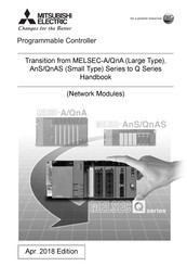
Mitsubishi Electric MELSEC-A Series Manual (248 pages)
network modules
Brand:
Mitsubishi Electric
| Category:
Controller
| Size: 6.37 MB
Table of Contents
Safety Precautions
3
Conditions of Use for the Product
10
Revisions
11
Table of Contents
12
Generic Terms and Abbreviations
16
Chapter 1 Introduction
18
Transition from MELSECNET (II) and /B to MELSECNET/H
18
Transition to the Q Series
18
Transition Procedure to a Q Series MELSECNET/H System
30
Replacement Selection Points
31
Replacement of the MELSECNET/10 for A/Ans/Qna/Qnas Series with the MELSECNET/H for Q Series
33
Replacing the CC-Link for A/Ans/Qna/Qnas Series with the CC-Link for Q Series
37
Chapter 2 Replacement of Melsecnet (II) and /B (Plc to Plc Network)
38
List of MELSECNET (II) and /B Alternative Models
38
Chapter 6 Replacement of CC-Link
40
Performance Specifications Comparisons
40
Module Performance Comparisons
40
Cable Performance Comparisons
44
Functional Comparisons
47
Switch Settings Comparisons
48
Parameter Comparisons
49
Example of Changing Parameters on 2-Tier System
50
Example of Changing Parameters on 3-Tier System (When Only the First Half of Link Parameter Is Set)
64
Example of Changing Parameters on 3-Tier System (When the First Half/Second Half of Link Parameter Is Set)
80
Program Comparisons
100
Comparison of Special Relays M (SB) and Special Registers D (SW)
100
Transient Instructions
102
Replacement Precautions
109
Chapter 3 Replacement of Melsecnet (II) and /B (Remote I/O Network)
113
List of MELSECNET (II) and /B Alternative Models
113
Performance Specifications Comparisons
115
Module Performance Compatibility Comparisons
115
Cable Performance Comparisons
120
Functional Comparisons
122
Switch Settings Comparisons
123
Parameter Comparisons
124
Parameter Change Example
125
Program Comparisons
135
Comparison of Special Relays M (SB) and Special Registers D (SW)
135
Transient Instructions
139
Replacement Precautions
140
Chapter 4 Replacement of the Melsecnet/10 (Plc to Plc Network)
142
List of MELSECNET/10 Alternative Models
142
Performance Specifications Comparisons
143
Module Performance Comparisons Incompatible
143
Cable Performance Comparisons
149
Functional Comparisons
151
Switch Settings Comparisons
155
Parameter Comparisons
156
Program Comparisons
159
Comparison of Link Special Relay (Sb)/Link Special Register (SW)
159
Comparison of Dedicated Instructions
162
Other Precautions
166
Chapter 5 Replacement of the Melsecnet/10 (Remote I/O Network)
167
Replacing MELSECNET/10 with MELSECNET/H
167
List of MELSECNET/10 Alternative Models
167
Performance Specifications Comparisons
169
Functional Comparisons
184
Switch Setting Comparisons
188
Parameter Comparisons
190
Program Comparisons
195
Comparison of Dedicated Instruction
196
Other Precautions
201
Gradually Replacing a Series Remote I/O Stations with Q Series Remote I/O Stations
202
List of MELSECNET/10 Modules and the Alternative Modules
202
Module Performance Specifications Comparisons
204
Functional Comparisons
207
Switch Setting Comparisons
208
Parameter Comparisons
209
Program Comparisons
210
Last Stage of the Replacement
213
Comparison of I/O Signals
225
Buffer Memory Comparisons
229
Comparison of Link Special Relay (Sb)/Link Special Register (SW)
231
Other Precautions
237
Parameter Setting Example
238
Parameter Setting Example on the A/Ans Series
238
Parameter Setting Example on the Q Series
240
Appendices
241
Appendix 1 External Dimensions
241
Appendix 2 Spare Parts Storage
241
Appendix 3 Related Manuals
243
Appendix 3.1 Replacement Handbooks
243
Appendix 3.2 A/Ans Series
244
Appendix 3.3 Qna/Qnas Series
244
Appendix 3.4 Q Series
244
Advertisement
Mitsubishi Electric MELSEC-A Series User Manual (204 pages)
Brand:
Mitsubishi Electric
| Category:
Controller
| Size: 5.07 MB
Table of Contents
Table of Contents
6
1 Introduction
10
General Description of Operation
10
ON/OFF Data Communication between the A2C and the Remote I/O Module
10
Features
13
General Terms and Abbreviations
17
Reference Manuals
19
2 System Configuration
20
Overall Configuration
20
Notes on System Construction
22
System Equipment
27
Modules Which Can be Connected to the A2CCPU
27
Peripheral Devices
34
3 General Specifications
36
4 A2Ccpu
37
Performance
37
Repeated Operation Processing
40
In~Ial Processing
40
END Processing
41
Timer Processing and Accuracy
42
Counter Processing and Maximum Counting Speed
44
Operation Processing at Momentary Power Failure
45
Scan Time
46
Watch Dog Timer (Wdl)
47
RUN. STOP. PAUSE Operation Processing
49
Functions
54
Constant Scan
55
Power Failure Compensation for Device Data in the A2C (LATCH Function)
58
Running and Stopping the A2C from External Devices (Remote RUN/STOP Function)
60
Status Latch
64
Sampling Trace
66
Offline Sw~Ch Function
69
Setting Priority for ERROR LED Indication
71
Control Functions of Remote I/O Modules and Remote Terminal Modules
73
4.2.10 Output from the ERR Terminals
77
Fault Detection
78
Fault Detection with Annunciator (F)
83
Memory Capacity Setting
89
Operation Mode at an Occurrence of Error
91
STOP -+ RUN Output Mode
92
Entry Code Registration
93
Print Title Registration
93
Devices
94
Device List
94
Instructions
96
Sequence Instructions
96
Basic Instructions
98
Application Instructions
104
Precautions on Handling
112
Part Identification 4 - N
113
Part Identification
113
4.10.1 External View of A2CCPUP21/R21
120
4.10.2 Setting for MELSECNET Data Link
128
5 MEMORY Ica, BATTERY, CABLES and DIN ADAPTER
131
Memory Ics
131
Specifications
131
Handling Instructions
131
Installation
131
Battery
133
Handling Instructions
133
Cables
135
DIN Adapter
137
Specifications
137
Handling Instructions
137
Fixing a DIN Adapter to a Module
139
Mounting to the DIN Rail
140
6 Loading and Installation 6 -1
141
Fail-Safe Circuit
141
Installation Environment
141
Calculation of Heat Generated by the A2C System
142
Wiring
144
Wiring Instructions
144
Connection between Modules
148
Installing the A2CCPU
151
7 Test Run
152
Check Points before Test Run
152
Test Run Procedures
154
8 Maintenance and Inspection
156
Daily Inspection
156
Periodic Inspection
157
Replacement of Battery
158
Battery Ike
158
Replacing Procedures
159
9 Troubleshooting
160
Basic Troubleshooting
160
Troubleshooting Flow Charts
161
Flow Chart Used When "POWER" LED of the A2CCPU Has Turned off
162
Flow Chart Used When "RUN" LED of the A2CCPU Has Turned off
163
Flow Chart Used When "RUN" LED of the A2CCPU Flickers
164
Flow Chart Used When "ERROR" LED Has Turned on
165
Flow Chart Used When "ERROR" LED of the A2CCPU Flickers
167
Flow Chart Used When "RD/SD" Leos of the A2CCPU Do Not Flicker
168
Flow Chart Used When Output Load of Output Module Does Not Turn on
169
Error Code Ust
171
Error Code List
171
App
175
APPENDIX 2 Ustof Specialrelays
184
APPENDIX 3 List of Special Registers APP
184
APPENDIX 4 Instructions for Use with Peripheral Devices APP
194
Mitsubishi Electric MELSEC-A Series User Manual (104 pages)
CC-Link System RS-232 Interface Module
Brand:
Mitsubishi Electric
| Category:
Controller
| Size: 3.87 MB
Table of Contents
Safety Precautions
3
Conditions of Use for the Product
9
Revisions
10
Table of Contents
11
About Manuals
13
Compliance with the Emc and Low Voltage Directives
14
How to Use Manuals
15
Generic Terms and Abbreviations
18
Definitions of Terminology
20
Packing List
21
Chapter 1 Overview
22
Features
23
Chapter 2 System Configuration
27
System Configuration
27
Applicable System
28
Precautions for System Configuration
29
Checking the Hardware Version
34
Checking the Production Number (SERIAL)
34
Chapter 3 Specifications
35
General Specifications
35
Performance Specifications
36
Function List
37
CC-Link Dedicated Cable Specifications
38
RS-232 Interface Specifications
39
RS-232 Connector Specifications
39
RS-232 Cable Specifications
39
General-Purpose I/O Specifications
40
Remote I/O and Remote Register
41
Remote I/O List
41
Remote I/O Details
43
Remote Register List
44
Buffer Memory
46
Buffer Memory List
46
Chapter 4 Functions
48
Selecting Mode and Function(S)
48
MELSOFT Connection Function
49
Accessible Range
51
Chapter 5 Preparatory Procedures and Setting
53
Implementation and Installation
53
Handling Precautions
53
Preparatory Procedures and Setting
53
Installation Environment
56
Part Names and Settings
56
AJ65BT-R2N Single Unit Test
62
Hardware Test
62
Wiring
64
CC-Link Dedicated Cable Connection Method
64
External Device Connection Method
65
Chapter 6 Melsoft Connection Mode Setting
67
Setting When LCPU Is Used
68
Switch Settings of each Station
69
Parameter Setting
70
Connection Target Setting
72
Setting When QCPU (Q Mode)/Qnacpu Is Used
73
Switch Settings of each Station
74
Parameter Setting
76
Connection Target Setting
79
Setting When ACPU/QCPU (a Mode) Is Used
81
Switch Settings of each Station
82
Parameter Setting
84
Connection Target Setting
87
Chapter 7 Troubleshooting
88
Troubleshooting When Using the MELSOFT Connection Function
89
Error Code List
94
Appendices
95
Appendix 1 Differences between AJ65BT-R2N and AJ65BT-G4-S3
95
Appendix 1.1 Specifications Comparisons
95
Appendix 1.2 Procedures and Precautions for Replacing AJ65BT-G4-S3 with AJ65BT-R2N
97
Appendix 2 External Dimensions
98
Appendix 3 RS-232 Interfaces Used for the AJ65BT-R2N
98
Advertisement
Mitsubishi Electric MELSEC-A Series User Manual (88 pages)
Brand:
Mitsubishi Electric
| Category:
Controller
| Size: 1.74 MB
Table of Contents
Table of Contents
12
1 Specifications
15
2 Performance Specifications
16
3 Emc Directives and Low Voltage Directives
17
Requirements for Compliance with EMC Directives
17
EMC Standards
18
Installation Instructions for EMC Directive
19
Cables
20
Power Supply Module
25
Ferrite Core
26
Noise Filter (Power Supply Line Filter)
27
Power Line for External Power Supply Terminal
27
Requirements for Compliance with Low Voltage Directives
28
Standard Applied for MELSEC-Ans Series Programmable Controller
28
Precautions When Using the MELSEC-Ans Series Programmable Controller
28
Power Supply
29
Control Panel
29
Module Installation
30
Grounding
30
External Wiring
30
4 Loading and Installation
31
Installing the Module
31
Notes on Handling the Module
31
Installation Environment
32
Notes on Installing the Base Unit
33
Fail-Safe Circuit Concept
36
Wiring
42
Performance Specifications for the A1SJHCPU Built-In Power Supply
42
The Precautions on the Wirings
44
Wiring to Module Terminals
49
Precautions When Connecting the Uninterruptible Power Supply (UPS)
50
Parts of the CPU
51
5 Specification and Connection of I/O Modules
54
Input Modules
54
Input Module Specifications
54
Input Module Connections
56
Output Modules
60
Output Module Specifications
60
Output Module Connections
64
Input/Output Combined Modules
72
Input/Output Combined Module Specifications
72
Input/Output Composite Module Connections
74
6 Error Codes
77
Error Code List
77
Appendices
86
Appendix 1 CPU-By-CPU Startup Names
86
Appendix 2 Transportation Precautions
86
Appendix 2.1 Relevant Models
86
Appendix 2.2 Transportation Guidelines
86
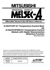
Mitsubishi Electric MELSEC-A Series User Manual (34 pages)
Temperature Control Module, Temperature Control Module with Heater Disconnection Detection Function (Hardware)
Brand:
Mitsubishi Electric
| Category:
Control Unit
| Size: 0.41 MB
Table of Contents
Table of Contents
4
Safety Precautions
5
About this Manual
9
1 General Description
10
2 Performance Specification
11
3 Name of each Part
16
4 Handling
18
Precaution When Handling
18
5 Wiring
19
Precaution When Wiring
19
Module Connection Example
20
6 External Dimensions
22
A1S64Tcrt-S1
22
A1S64Tcrtbw-S1
23
7 Appendix
24
Appendix 1. I/O Signal List
24
Appendix 2. Buffer Memory Allocation
25
Appendix 3. Alert Occurrence Details
28
Appendix 4. Error Code List
30
Appendix 5. Troubleshooting
32
Appendix 5.1 Handling the A1S64TC Errors
32
Appendix 5.2 When the A1S64TC RUN LED Flashes or Turns off
33
Appendix 5.3 When the ALM LED Is Turned on or Flashing
33
Appendix 5.4 When the Temperature Adjustment Ready Flag(X1) Is Not Turned on
34
Appendix
34
When the Write Data Error Flag (X2) Is on
34
When the H/W(Hardware) Error Flag (X3) Is on
34
When the Alert Flag (XC to XF) Is on
34
Mitsubishi Electric MELSEC-A Series User Manual (16 pages)
Digital-Analog Conversion Module
Brand:
Mitsubishi Electric
| Category:
Media Converter
| Size: 0.35 MB
Advertisement
Related Products
Mitsubishi Electric MELSEC iQ-R AnyWireASLINK
Mitsubishi Electric Melsec-QJ71E71-100
Mitsubishi Electric Melsec-QJ71E71-B5
Mitsubishi Electric Melsec-QJ71E71-B2
Mitsubishi Electric Melsec-LJ71E71-100
Mitsubishi Electric MELSEC-Q62HLC
Mitsubishi Electric MELSEC-GX Configurator-TC
Mitsubishi Electric MELSEC-LD77MS2
Mitsubishi Electric MELSEC-LD77MS4
Mitsubishi Electric MELSEC-LD77MS16
Mitsubishi Electric Categories
Air Conditioner
Controller
Projector
Inverter
Heat Pump
More Mitsubishi Electric Manuals
Login
Sign In
OR
Sign in with Facebook
Sign in with Google
Upload manual
Upload from disk
Upload from URL