Sign In
Upload
Manuals
Brands
HP Manuals
Test Equipment
8920A
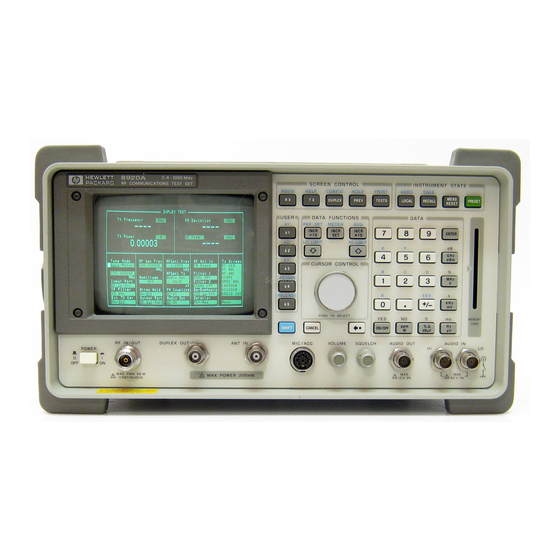
HP 8920A Communications Test Set Manuals
Manuals and User Guides for HP 8920A Communications Test Set. We have
4
HP 8920A Communications Test Set manuals available for free PDF download: User Manual, Programmer's Manual, Application Handbook
HP 8920A User Manual (659 pages)
RF Communications Test Set
Brand:
HP
| Category:
Test Equipment
| Size: 4.75 MB
Table of Contents
Notice
2
Safety Symbols
4
Safety
4
Safety Earth Ground
4
General
4
Safety Considerations for this Instrument
5
Hewett-Packard Warranty Statement for Commercial Products
7
Contents
13
Table of Contents
15
Before Connecting a Radio
40
Connecting a Radio to the Test Set
40
List of Screens
41
Accessing the Test Set’s Screens
41
Accessing Screens
42
Changing a Field’s Setting
43
Different Types of Fields
43
Unit-Of-Measure Field
44
Underlined Immediate-Action Field
44
To Change an Underlined Entry
44
To Change a Unit-Of-Measure
44
To Change a Value
45
To Make a One-Of-Many Choice
45
Numeric-Entry Field
45
One-Of-Many Field
45
How Do I Verify that the Test Set Is Operating Properly?
46
Instrument Quick Check
46
Instrument Functional Diagram
47
Configuring Your Test Set
49
General Operating Information
50
To Set Screen Intensity
50
To Set RF Voltage Interpretation (50 /Emf)
50
To Set the Date and Time
50
To Change the Beeper Volume
51
To Verify or Change the Low-Battery Setting
51
Operating Overview
53
Example of How Global Fields Work
54
Interaction between Screens
54
Priority RX TEST and TX TEST Fields
55
Example of How Priority Fields Work
56
Where to Access Measurements
57
Displaying Measurements
57
Transmitter Frequency Error
58
Transmitter Power
58
Transmitter Frequency
58
Displaying RF Measurements
58
Displaying AF Measurements
59
FM Deviation, am Depth, AC Level
59
AF Measurements Selected by AF Analyzer Input Setting
59
SINAD, Distortion, SNR, AF Frequency, DC Level, DC Current
60
AF Power
60
To Change the Measurement’s Unit-Of-Measure
61
To Use the Analog METER Format
62
To Make Beat Frequency Measurements
62
Decimal Values
63
Entering and Changing Numbers
63
Hexadecimal Values
64
Entering the Unit-Of-Measure for Settings
64
Changing the Unit-Of-Measure for Settings
64
To Enter and Change the Unit-Of-Measure
64
To Change the Increment or Decrement Setting
65
Using the Pre-Defined Increment/Decrement Keys
65
Specifying an Increment Value
65
Example of Setting an Increment Value
65
To Print a Screen’s Contents
66
Printing a Screen
66
To Set a HI And/Or lo LIMIT
67
Using Measurement Limit Indicators
67
To Reset or Remove Limits
68
To Remove a Limit
68
Example of Setting HI and lo Limits
68
To Reset a Limit that Has Been Exceeded
68
To Use Measurement Averaging
69
Example of Using Measurement Averaging
69
Averaging Measurements
69
To Use the Present Value as a Reference
70
To Set a Specific Reference
70
Setting a Measurement Reference
70
Memory Card Part Numbers
71
Using Memory Cards
71
Inserting and Removing Memory Cards
72
Inserting a Memory Card
72
Setting the Write-Protect Switch
73
Setting the SRAM Write-Protect Switch
73
The Memory Card Battery
74
Replacing the Battery
74
Replacing the Memory Card’s Battery
74
Memory Card Initialization
75
To Recall an Instrument Setup
76
To Save an Instrument Setup
76
Saving and Recalling Instrument Setups
76
Example of Saving and Recalling an Instrument Setup
77
To Remove (Clear) an Individual Save Register
77
To Clear All Save Registers
78
Register Names
78
POWERON Settings
78
BASE Settings
79
Memory Considerations
79
Instrument Hardware Changes
79
Using USER Keys
80
An Example of Pre-Assigned Local User Keys
81
To Use the Pre-Assigned Local USER Keys
81
To Assign Local USER Keys
82
To Release Local USER Keys
82
Example of Assigning a Local USER Key
82
To Assign Global USER Keys
83
To Release Global USER Keys
83
Example of Assigning a Global USER Key
83
To Set an RF Offset
84
Example of Setting an RF Offset
84
Setting an RF Generator/Analyzer Offset
84
Running IBASIC Programs from Memory Cards
85
Using HP-IB Control
85
Using Remote Control
85
Equivalent Front-Panel Control Characters
86
To Configure for Serial Port Operation
86
Using an ASCII Terminal
86
Adjacent Channel Power Screen
89
How the Test Set Measures Adjacent Channel Power (ACP)
90
ACP Meas
91
Field Descriptions
91
Operating Considerations
91
The Adjacent Channel Power Screen
91
Afgen1 Freq
92
Afgen1 to
92
Carrier Ref
92
Channel BW
92
Relationship between Tune Freq, Ch Offset, and Channel BW Fields
93
Ch Offset
94
Ext TX Key
94
Input Atten
94
Input Port
95
Lower and Upper ACP [Ratio:level]
95
Res BW
96
Tune Freq
96
Tune Mode
96
TX Freq Error/Tx Frequency
97
TX Power
97
TX Pwr Zero
97
AF Analyzer Screen
99
AF ANALYZER Functional Block Diagram
100
Block Diagram
100
AC Level
101
AF Anl in
101
AF Cnt Gate
102
AF Freq
102
AM Depth
103
Audio in lo
103
Current
103
DC Current
103
DC Level
104
De-Emp Gain
104
De-Emphasis
104
Distn
104
Detector
105
Detector Types
105
Ext Load R
106
Filter 1 and Filter 2
106
FM Deviation
106
Gain Cntl
107
Input Gain
107
Notch Freq
108
Notch Gain
108
Pk Det to
108
Scope to
109
Settling
109
Sinad
110
Snr
110
SNR Operation
110
Speaker ALC
111
Speaker Vol
111
TX Freq Error/ TX Frequency
111
Call Processing Subsystem
113
Description of the Call Processing Subsystem
114
Operational Overview
115
Call Processing State Diagram
116
Accessing the Call Processing Subsystem’s Screens
117
Call Processing Subsystem’s Screens
117
Connecting a Mobile Station
118
Using the Call Processing Subsystem
118
Connecting a Mobile Station to the Test Set
119
600 Ohm Impedance
120
Mobile Station Audio out Impedance
120
Generalized Procedures Using the Call Processing Subsystem
121
The CALL CONTROL Screen
122
Access
123
Active
123
Amplitude
124
Called Number
124
CC Order
125
Ch Loc
125
Chan
125
Cntl Channel
126
Connect
126
Display
127
CALL CONTROL Screen with Decoding Error Message Display
128
AMPS CALL CONTROL Screen with Meas Selected
129
Dsat
130
NAMPS CALL CONTROL Screen with Meas Selected
130
DSAT/DST (Hex)
131
ESN (Dec)
131
ESN (Hex)
131
Handoff
132
MS ID
132
Order
134
Pwr Lvl
134
Phone Num
135
Register
135
Release
135
Sat
136
Scm
136
Sid
136
System Type
136
TX Freq Error
137
VC Order
139
Using the CALL CONTROL Screen to Test Call Processing Functions
140
Conditioning the Test Set for Call Processing
141
Configure the Test Set
142
Turn on the Test Set’s Control Channel
143
Register a Mobile Station
144
Page a Mobile Station
145
Paging a Mobile Station that Has Not Registered with the Test Set
146
Handoff a Mobile Station to a New Voice Channel
147
Release a Mobile Station
147
Change the Transmit Power Level of a Mobile Station
148
Originate a Call from a Mobile Station
149
Send an Alert Order to a Mobile Station
150
Using the CALL CONTROL Screen to Test AMPS Authentication
151
Condition the Test Set for Call Processing
152
Initialize Call Processing with Authentication
154
Initializing Authentication Without Registration
155
Page a Mobile Station with Authentication
156
Paging a Mobile Station that Has Registered with the Test Set
156
Originate a Call with Authentication
157
Perform an SSD Update
158
Performing an SSD Update on the Control Channel
158
Performing an SSD Update on the Voice Channel
159
Perform a Unique Challenge
160
Performing a Unique Challenge on the Control Channel
160
Performing a Unique Challenge on the Voice Channel
161
AUTHENTICATION Screen
162
Authent
163
A_Key
163
Esn
163
Rand_A
163
Randssd_1
164
Randssd_2
164
Randssd_3
164
Rand_U
164
CALL DATA Screen
165
NRVC Ord - Narrow Order or Order Confirmation Message
166
Rvcordcon - Reverse Voice Channel Order Confirmation Message
166
Display Word
167
CALL DATA Screen Message Field Descriptions
170
Nawc
170
RECCW a Message Fields
170
RECCW B Message Fields
172
RECCW C Message Fields
174
RECCW D Message Fields
175
RECCW E Message Fields
176
Rvcordcon Message Fields
177
Bschalord Message Fields
178
Ordq
178
Parity
178
Rsvd
178
Authword Message Fields
179
Count
179
Randbs
179
Authr
180
Uniqchcon Message Fields
180
Rvcord Message Fields
181
Rvcbschal Message Fields
182
NRVC Ord Message Fields
183
Using the CALL DATA Screen
186
To View the Decoded Reverse Channel Words from a Mobile Station Page
187
To View the Decoded Reverse Channel Words from Mobile Station Handoff
189
To View the Decoded Reverse Channel Words from Mobile Station Release
191
To View the Reverse Channel Words from a Mobile Station Origination
193
CALL BIT Screen
194
FVC O Mes - FVC Mobile Station Control Order Message
196
Message Contents that Can be Modified Using the CALL BIT Screen
196
Data Spec
198
CALL BIT Screen Message Field Descriptions
201
SPC WORD1 Message Fields
201
DCC
202
SPC WORD2 Message Fields
202
T1T2
202
ACCESS Message Fields
204
REG INC Message Fields
206
REG ID Message Fields
208
C-FILMESS Message Fields
210
MS WORD1 Message Fields
212
Msmessord Message Fields
213
MS Intvch Message Fields
214
FVC O Mes Message Fields
215
FVC V Mes Message Fields
217
Randchala Message Fields
219
Randchalb Message Fields
220
RAND SSD1 Message Fields
221
RAND SSD2 Message Fields
222
RAND SSD3 Message Fields
223
Bschalcon Message Fields
224
Uniqchord Message Fields
225
FVC SSD1 Message Fields
226
FVC SSD2 Message Fields
227
FVC SSD3 Message Fields
228
Fvcbscon Message Fields
229
Fvcuniqch Message Fields
230
EXT PROT Message Fields
231
NCH ASN Message Fields
232
NMS FVC Message Fields
233
WNHO MESS Message Fields
235
NHO MES Message Fields
236
Selecting the Message Content Generation Method
239
Using the CALL BIT Screen
239
System Operation When Data Spec Field Set to Std
240
System Operation When Data Spec Field Set to Bits
241
Changing the Content of a Message Field
242
Typical Example
243
ANALOG MEAS Screen
244
Using the ANALOG MEAS Screen
247
To Make an RF Sensitivity Measurement
248
To Make an FM Hum and Noise Measurement
249
CALL CONFIGURE Screen
250
Configure Screen
253
Antenna in
255
Base Freq (User Defined)
255
Beeper
257
Chan Space
257
Date
258
Duplex out
258
Firmware
258
Low Battery
260
Notch Coupl
260
Range Hold
260
RF Chan Std
262
RF Display
263
RF Gen Volts
264
RF In/Out
264
RF Level Offset
265
RF Offset
265
RX/TX Cntl
266
Time
267
Total RAM
267
Signaling Decoder Screen
269
Decoder Frequency Measurements
270
Field Descriptions for Decoder Modes
270
The Decoder’s Signal Source
270
AMPS-TACS, NAMPS-NTACS Decoder
271
Decoder Mode Differences
271
The NAMPS-NTACS Voice Channel Decoder
272
Gate Time
273
Input Level
273
Num of Bits
274
Polarity
274
RECC Data (NAMPS-NTACS: RECC)
274
Single/Cont
275
Stop Meas
275
Trig Level
275
Trigger Pattern (Bin)
275
Decoding the Reverse Control Channel (RECC) Data
276
Interaction with the Encoder
276
Using the AMPS/TACS, NAMPS/NTACS Decoder
276
Decoding AMPS-TACS Reverse Voice Channel (RVC) Data
277
Decoding NAMPS-NTACS Reverse Voice Channel (RVC) Data
277
Interpreting Decoded Data
278
NAMPS-NTACS Reverse Voice Channel Measurements
279
Continuous Digital Controlled Squelch System Decoder
280
The CDCSS Sequence Decoder Screen
280
Arm Meas
281
Code (Oct)
281
Data (Bin)
281
Data Rate
281
AF Analyzer Settings
284
Using the CDCSS Decoder
284
Digital Paging Decoder
285
The Digital Paging Decoder Screen
285
Dual-Tone Multi-Frequency (DTMF) Decoder
289
The DTMF Decoder Screen
289
Measurement Limits
294
Using the DTMF Decoder
294
EDACS Decoder
295
The EDACS Trunked Radio Decoder Screen
295
EDACS Transmitter Testing
298
Preset the Test Set
298
Transmitter Test Procedure
298
Using the EDACS Decoder
298
Define the Control Channel Settings
299
Prepare the Decoder for Transmitter Measurements
299
Make Basic Transmitter Measurements
300
Making Other Transmitter Measurements
300
Function Generator Decoder
301
The Function Generator Decoder Screen
301
Decoding Considerations
304
Using the Function Generator Decoder
304
LTR Decoder
305
The LTR Trunked Radio Decoder Screen
305
Decoding Mobile Radio Signaling Data
309
Using the LTR Decoder
309
Decoding Repeater Signaling Data
310
If no Decoded Data Is Displayed
310
MPT 1327 Decoder
311
The MPT 1327 Decoder Screen
311
Decoder Triggering
312
Manually Decoding MPT 1327 Signals
312
Triggering the MPT 1327 Decoder
313
Detecting and Querying Messages
314
NMT Decoder
316
The NMT Decoder Screen
317
Frame Log
318
Type
318
Load Test
319
Run Test
320
Standard
320
Fields Used with Different Standards
321
General Encoder Operation
321
Testing a BS or MTX
321
Using the NMT Decoder/Encoder
321
General Decoder Operation
322
Manual Testing of NMT Radios
323
Automated NMT Radio Tests
324
Required Test Set Settings
324
RF Analyzer Settings
324
RF Generator Settings
324
Special Frame Suffixes
325
Creating NMT Tests
326
Entering Tests into the Decoder’s RAM
327
Using Direct Command Entry
328
Programming Using an External Computer
329
Copying Programs to Mass Storage
330
Downloading a Program into IBASIC Controller RAM
330
Downloading Programs
330
Begin
331
End
331
EXIT N
331
Program Command Syntax
331
GOTO L
332
RCHAN C
332
TCHAN C
332
IF F L
333
SEND F
333
SEND F N
333
Valid Channel Assignments
333
Clear
334
REPEAT N L
334
SET N M
334
WAIT N
334
The Tone Sequence Decoder Screen
335
Tone Sequence Decoder
335
Freq
336
Freq Error
336
Duplex Test Screen
339
DUPLEX TEST Functional Block Diagram
340
The Duplex Test Screen
341
Atten Hold
345
Audio out
346
IF Filter
349
Output Port
350
Signaling Encoder (AF Generator 2)
353
Field Descriptions for Encoder Modes
354
AMPS-TACS NAMPS-NTACS Encoder
355
AMPS-TACS/NAMPS-NTACS Mode Forward Control Channel (FOCC)
355
Control and Voice Channel Identifiers
355
AMPS-TACS Mode Forward Voice Channel (FVC)
356
NAMPS-NTACS Mode Forward Voice Channel (FVC)
356
B/I Delay (FOCC)
357
Bursts
357
Busy/Idle (FOCC)
357
Dsat (Fvc)
358
AMPS-TACS/NAMPS-NTACS FOCC Message and Filler Data Format
359
Filler (FOCC)
359
FM Coupling
360
Message (FOCC)
361
AMPS-TACS FVC Message Data Output Format
362
Message (FVC)
362
NAMPS-NTACS FVC Message Data Output Format
363
Message/Dst (FVC)
364
SAT Freq (FVC)
365
SAT Level (FVC: AMPS-TACS)
365
Send DSAT (FVC)
365
Send Filler (FOCC)
365
Automated Test Software
367
Encoder/Decoder Interaction
367
Using the AMPS-TACS, NAMPS-NTACS Encoder
367
CDCSS Encoder
368
The CDCSS Encoder Mode Screen
368
Afgen2 to
369
CDCSS Data Stream Bit Assignments
372
The CDCSS Data Stream
372
Using the CDCSS Encoder
372
Digital Paging Encoder
373
The Digital Paging Encoder Mode Screen
373
Mssg Length
375
Pager Alpha-Numeric Message
376
Pager Numeric Message
376
Send Mode
377
DTMF Sequence Encoder
378
The DTMF Sequence Encoder Mode Screen
378
Pre-Emp
380
Symbol Frequencies (Hz)
380
Examples of Twist and Pre-Emphasis Interaction
381
Twist
381
Twist and Pre-Emphasis Interaction
381
EDACS Encoder
382
The EDACS Trunked Radio Encoder Mode Screen
382
Logical ID
385
Signaling Dev
386
Site ID
386
Sub-Audible Dev
387
Working Channel, Number
387
Working Channel: RX Frequency
387
Using the EDACS Encoder
388
Testing EDACS Mobiles
389
Testing the Mobile’s Receiver
389
Testing the Mobile’s Transmitter
389
Connect the Mobile to the Test Set
390
Mobile Receiver Test Procedure
390
Get the Mobile up on the Control Channel
391
Make Receiver Measurements
392
Function Generator Encoder
393
The Function Generator Encoder Screen
393
Afgen2 Freq
394
Waveform
395
LTR Encoder
396
The LTR Trunked Radio Encoder Mode Screen
396
How Message 1 and Message 2 Fields Are Used to Create Trunking Data
400
Using the LTR Encoder
400
Radio Test Examples
401
To Test Your Receiver
401
To Make a 12 Db SINAD Measurement
402
To Test Your Transmitter
402
Performing Channel Changes
403
Address Qualifier
404
MPT 1327 Encoder
404
The MPT 1327 Trunked Radio Encoder Mode Screen
404
Aloha Number
405
Aloha Number Encoding for 4-Bit Aloha Numbers
405
Control Channel
406
Test Mode
406
Delay Parameter for Repeat Transmissions
407
Delay Parameter to Actual Response Delay
407
Traffic Channel
407
Undisplayed Controls
407
Forward Control Channel Message and Filler Buffers
408
Sequence of Events in Assembling a Signaling Message
410
Encoder:mpt1327:Filler:clear N
411
Encoder:mpt1327:Filler:update
411
Forward Control Channel in Control Mode and Not Sending
411
Encoder:mpt1327:Message:control:data N,String
412
Encoder:send
412
Encoder:stop
412
Forward Control Channel in Control Mode and Sending
413
Control and Traffic Channel Message Structures
414
Traffic Channel Message Generation
414
Forward Control Channel Message Structure
415
Traffic Channel Message Structure
415
Signaling Mode Transitions Table
416
Manually Testing MPT 1327 Radios
417
Using Automated Test Software
417
Using the MPT 1327 Encoder
417
Radio Unit under Test
418
System Identity
418
Simulated Calling Unit
419
Nordic Mobile Telephone (NMT) Encoder
420
The NMT Encoder Screen
420
Access Channel Number
421
Access Channel Power
421
Add Info
421
Audio Frequency Generator 2 to Contains Two Fields
422
NMT Additional Information Bits
422
Alarm Level High
423
Alarm Level Low
423
Batt Save
424
BS Identity
424
Calling Channel Number
425
Calling Channel Power
425
Dut
426
Meas Ch #
426
Meas Field Strength
427
Mgmt/Maint
427
Msn
427
Phi Signal
427
Password
428
SIS Challenge
428
SIS Response
428
Tci
429
Traffic Area - Alt
429
Traffic Area - Main
430
Traffic Channel (Alt) Number
430
Traffic Channel (Alt) Power
430
Traffic Channel (Main) Number
431
Traffic Channel (Main) Power
431
The Tone Sequence Encoder Mode Screen
432
Tone Sequence Encoder
432
Symbol Definition
434
Symbol Sequence
434
Help Screen
435
I/O Configure Screen
437
Data Length
439
HP-IB Adrs
439
IBASIC Echo
439
Inst Echo
439
Save/Recall
441
Serial Baud
441
Serial in
442
Stop Length
442
Xmt Pace
442
Message Screen
443
Oscilloscope Screen
445
The Oscilloscope Screen and Menus
446
Oscilloscope Main Functions
447
Oscilloscope Main Menu Fields
447
How the Oscilloscope Displays Measurements
448
Oscilloscope Marker Menu Fields
448
Marker Measurements
449
Reading Measurement Results at the Oscilloscope’s Markers
449
Oscilloscope Trigger Menu Fields
450
Oscilloscope Triggering
450
Cont/Single
451
Level (DIV)
451
Pre-Trig
451
Oscilloscope Input Indicator
452
Selecting the Oscilloscope’s Input
452
Using the Oscilloscope
452
Using the Scope to Field
452
Print Configure Screen
453
The Printer Configurations Screen
454
Radio Interface Screen
457
Data I/O
458
Radio Interface Functional Description
458
Audio Analyzer
459
Audio Source
459
External Transmitter Key Relay
459
Interrupt Capability
459
Field Descriptions
460
The Radio Interface Screen
460
Programmer’ Guide
461
I/O Config
462
Output Data
462
Parallel Data in
462
Strobe Pol
462
Setting the Radio Interface’s Logic Level
463
Using the Radio Interface (Manual Operation)
463
Inputting Data
465
Outputting Data
466
Using Interrupts
468
HP-IB Command Summary
469
Inputting Data over HP-IB
469
Using the Radio Interface (Remote Operation)
469
Outputting Data over HP-IB
470
Using Interrupts over HP-IB
470
RF Analyzer Screen
471
RF ANALYZER Functional Block Diagram
472
The RF Analyzer Screen
473
RF Cnt Gate
477
Sensitivity
477
Squelch
477
RF Generator Screen
483
RF GENERATOR Functional Block Diagram
484
The RF Generator Screen
485
Mod in to
489
RF Gen Freq
489
RX Test Screen
493
The RX Test Fields and Their Functions
494
The RX Test Screen
495
Service Screen
501
Counter Connection
502
Frequency
502
RAM Initialize
503
Spectrum Analyzer Screen
505
The Spectrum Analyzer Screen and Menus
506
Spectrum Analyzer Main Functions
507
Spectrum Analyzer Main Menu Fields
507
RF In/Ant
508
RF Generator Menu Fields, Fixed Operation
509
RF Generator Menu Fields, Tracking Operation
511
Using the Spectrum Analyzer with the Tracking Generator
511
Offset Freq
512
Port/Sweep
512
Spectrum Analyzer Marker Menu Fields
513
Reading Measurement Results at the Spectrum Analyzer’s Markers
514
Spectrum Analyzer Auxiliary Functions
515
Spectrum Analyzer Auxiliary Menu Fields
515
No Pk/Avg
517
Automatic Calibration
518
Relationship between Span, Resolution Bandwidth, and Sweep Rate
518
Setting Resolution Bandwidth and Sweep Rate
518
Using the Spectrum Analyzer
518
Tests Screen
519
Description of the Tests Subsystem
520
Tests Subsystem Screens
521
TESTS (Main Menu)
522
The TESTS (Main Menu) Screen
522
IBASIC IBASIC Cntrl
523
Proc Save/Delete Procedure
524
TESTS (Channel Information)
525
The TESTS (Channel Information) Screen
525
Delete Ch
526
Insert Ch
526
Main Menu
526
Print All
526
TESTS (Test Parameters)
527
The TESTS (Test Parameters) Screen
527
TESTS (Order of Tests)
528
The TESTS (Order of Tests) Screen
528
Delet Stp
529
Insrt Stp
529
TESTS (Pass/Fail Limits)
530
The TESTS (Pass/Fail Limits) Screen
530
TESTS (Save/Delete Procedure)
532
The TESTS (Save/Delete Procedure) Screen
532
Code Location
533
Enter Procedure Filename
533
Select Procedure Location
534
TESTS (Execution Conditions)
535
The TESTS (Execution Conditions) Screen
535
Autostart Test Procedure on Power-Up
536
If Unit-Under-Test Fails
536
TESTS (External Devices)
538
The TESTS (External Devices) Screen
538
External Disk Specification
539
TESTS (Printer Setup)
541
The TESTS (Printer Setup) Screen
541
TESTS (IBASIC Controller)
544
The TESTS (IBASIC Controller) Screen
544
ROM Programs
546
Using the Signal Strength Meter
546
The Signal Strength Meter Screen
546
Securing a Test Procedure
547
Clearing RAM
547
TX Test Screen
549
TX TEST Functional Block Diagram
550
The TX Test Screen
551
RF Channel
557
Connector, Key, and Knob Descriptions
561
Ant in
562
Connector Descriptions
562
Audio in
563
Audio Monitor Output
564
Crt Video Output
565
Chassis Ground
565
DC Current Measurement
565
DC Input
566
Digital Test Connections
566
Control I/O, CW RF OUT, DET OUT, IQ RF IN, 114.3 Mhz out
566
Ext Scope Trigger Input
567
MIC/Acc
568
MEMORY CARD Slot
568
Hp-Ib
568
To Use the Microphone
569
MIC/ACC Operating Considerations
569
MIC in Specifications
569
MIC/ACC Connections
570
Modulation Input
571
Parallel Port
571
Radio Interface
573
Pin Numbers for the Radio Interface Connector
573
Serial Port
577
Serial Port Connections
578
10 Mhz REF INPUT
579
10 Mhz REF OUTPUT
579
DATA Keys
580
DATA FUNCTIONS Keys
581
INSTRUMENT STATE Keys
582
SCREEN CONTROL Keys
582
Miscellaneous Keys and Buttons
583
USER Keys
583
Knob Descriptions
584
Modifications, Accessories, Manuals, Support
585
Modifications
586
Hardware Upgrades and Modifications
586
Accessories
589
External Monitor
591
Manuals (English and Non-English)
592
Radio Test Software
594
HP 11807A Software for the HP 8920A
594
Power Cables
595
HP Support for Your Instrument
602
Customer Training
602
Error Messages
605
General Information about Error Messages
606
Positive Numbered Error Messages
607
Negative Numbered Error Messages
608
IBASIC Error Messages
609
HP-IB Error Messages
610
Text Only Error Messages
611
The Message Display
612
Warbles and Beeps
612
Non-Recoverable Firmware Error
613
Required Hardware for Additional Test Set Functions
615
Index
621
Advertisement
HP 8920A Programmer's Manual (607 pages)
RF Communications Test Set
Brand:
HP
| Category:
Test Equipment
| Size: 4.59 MB
Table of Contents
Table of Contents
16
HP-IB Commands
93
HP-IB Syntax Diagrams
94
Adjacent Channel Power (ACP)
97
AF Analyzer
99
:Afgenerator1
102
AF Generator 2 Pre-Modulation Filters
103
AF Generator 2/Encoder
104
Configure, I/O Configure
119
Call Processing
124
Decoder
143
Display
147
Measure
149
Oscilloscope
156
Program
161
Save/Recall Registers
162
RF Analyzer
163
RF Generator
165
Radio Interface
166
Spectrum Analyzer
167
HP-IB Only Commands
169
Status
170
System
171
Tests
172
Trigger
175
Integer Number Setting Syntax
176
Real Number Setting Syntax
177
Multiple Real Number Setting Syntax
178
Number Measurement Syntax
179
Multiple Number Measurement Syntax
181
Equivalent Front-Panel Key Commands
182
IEEE 488.2 Common Commands
210
Common Command Descriptions
211
Triggering Measurements
230
Advanced Operations
239
Increasing Measurement Throughput
240
Status Reporting
246
HP-IB Service Requests
297
Instrument Initialization
307
Passing Control
320
Memory Cards/Mass Storage
331
Default File System
332
Mass Storage Device Overview
333
Default Mass Storage Locations
340
Mass Storage Access
342
DOS and LIF File System Considerations
343
Using the ROM Disk
350
Using Memory Cards
351
Backing up Procedure and Library Files
356
Copying Files Using IBASIC Commands
357
Using RAM Disk
359
Using External Disk Drives
361
IBASIC Controller
363
Introduction
364
The IBASIC Controller Screen
365
Important Notes for Program Development
367
Program Development
368
Interfacing to the IBASIC Controller Using Serial Ports
370
Choosing Your Development Method
384
Method #1. Program Development on an External BASIC Language Computer
386
Method #2. Developing Programs on the Test Set Using the IBASIC EDIT Mode
394
Method #3. Developing Programs Using Word Processor on a PC (Least Preferred)
399
Uploading Programs from the Test Set to a PC
406
Serial I/O from IBASIC Programs
407
Program Subsystem
410
The TESTS Subsystem
438
Programming the Call Processing Subsystem
445
Description of the Call Processing Subsystem's Remote User Interface
446
Using the Call Processing Subsystem's Remote User Interface
450
Programming the CALL CONTROL Screen
460
HP
8920A
Application Handbook
HP 8920A Application Handbook (322 pages)
RF Communications Test Set
Brand:
HP
| Category:
Test Equipment
| Size: 6.01 MB
Table of Contents
Table of Contents
22
The Test Set's Features
30
Screen Control Keys" on Page
37
Instrument State Keys" on Page
38
Non-Bracketed Keys and Memory Card Slot" on Page
41
The Test Set's Rear-Panel Features
42
Key and Fuse Holders" on Page
43
Section 3
53
Carrier Frequency
55
FM off the Air Monitoring/Determining Unknown Transmitter
55
FM Output Power, Deviation, and Frequency/Frequency Error
58
Measurement
60
FM Deviation and Symmetry Measurement
61
FM Microphone Sensitivity and Modulation Limiting Measure
64
FM CTCSS Encoder Frequency and Deviation Measurement" on
67
FM CDCSS Coding and Deviation Measurements
69
FM DTMF Encodes and Deviation Measurement
72
FM Audio Distortion Measurement
76
FM Harmonics and Spurious Output Measurement
78
FM Audio Output Power Measurement
82
FM SINAD, Receiver Center Frequency, and Modulation Accep
85
FM Variation of Sensitivity with Signal Frequency Measure
89
FM 20 Db Quieting Sensitivity Measurement
93
FM Critical and Maximum Squelch Sensitivity Measurement
96
FM CTCSS Sensitivity and Bandwidth Measurement
99
FM CDCSS Sensitivity Measurement
103
FM Audio Frequency Response Measurement
107
FM Audio Distortion Measurement
110
FM Spurious Response Attenuation Measurement
113
Section 4
119
AM off the Air Monitoring/Determining Unknown Transmitter
121
Carrier Frequency
121
AM Output Power, Deviation, and Frequency/Frequency Error
124
Measurement
126
AM Microphone Sensitivity and Modulation Limiting Measure
127
AM Audio Distortion Measurement
130
AM Harmonics and Spurious Output Measurement
132
AM Envelope Display Measurement
135
AM Receiver
138
AM Audio Output Power Measurement
139
AM Sensitivity Measurement
142
AM AGC Measurement
145
AM Squelch Sensitivity Measurement
148
AM Audio Frequency Response Measurement
151
AM Audio Distortion Measurement
154
AM Spurious Response Attenuation Measurement
157
List of Measurements
191
Measuring Transmitter High/Low Power Signals
193
Spectrum Analyzer Measurements
193
Field Strength Measurements
198
Analyzing External Transmitter Inter-Modulation Distortion
202
Basic Measurements with the Tracking Generator
208
1/4 Wave Coaxial Filter Tuning (Swept)
216
Cable Fault Locations
220
Repeater System Effective Sensitivity Measurement
230
Signal Generator Specifications
257
Audio Source Specifications
263
RF Analyzer Specifications
264
AF Analyzer Specifications
270
Oscilloscope Specifications
273
Spectrum Analyzer Specifications (Option 102)
274
Signaling (Option 004)
278
DC Current Meter (Option 103)
279
Remote Programming (Option 103)
280
Reference Oscillator Specifications
281
Save/Recall Registers
282
General Specifications
283
Advertisement
HP 8920A Application Handbook (319 pages)
RF Communications Test Set
Brand:
HP
| Category:
Test Equipment
| Size: 2.22 MB
Table of Contents
Table of Contents
20
Screen Control Keys" on Page
35
Instrument State Keys" on Page
36
Non-Bracketed Keys and Memory Card Slot" on Page
39
The Test Set's Rear-Panel Features
40
Key and Fuse Holders" on Page
41
Carrier Frequency
53
Measurement
58
FM Deviation and Symmetry Measurement
59
FM CTCSS Encoder Frequency and Deviation Measurement" on
65
FM CDCSS Coding and Deviation Measurements
67
FM DTMF Encodes and Deviation Measurement
70
FM Audio Distortion Measurement
74
FM Harmonics and Spurious Output Measurement
76
FM Audio Output Power Measurement
80
FM 20 Db Quieting Sensitivity Measurement
91
FM Critical and Maximum Squelch Sensitivity Measurement
94
FM CTCSS Sensitivity and Bandwidth Measurement
97
FM CDCSS Sensitivity Measurement
101
FM Audio Frequency Response Measurement
105
FM Audio Distortion Measurement
108
FM Spurious Response Attenuation Measurement
111
Carrier Frequency
119
Measurement
124
AM Audio Distortion Measurement
128
AM Harmonics and Spurious Output Measurement
130
AM Envelope Display Measurement
133
AM Audio Output Power Measurement
137
AM Sensitivity Measurement
140
AM AGC Measurement
143
AM Squelch Sensitivity Measurement
146
AM Audio Frequency Response Measurement
149
AM Audio Distortion Measurement
152
AM Spurious Response Attenuation Measurement
155
Spectrum Analyzer Measurements
191
Measuring Transmitter High/Low Power Signals
191
Field Strength Measurements
196
Analyzing External Transmitter Inter-Modulation Distortion
200
Basic Measurements with the Tracking Generator
206
1/4 Wave Coaxial Filter Tuning (Swept)
214
Signal Generator Specifications
255
Audio Source Specifications
261
RF Analyzer Specifications
262
AF Analyzer Specifications
268
Oscilloscope Specifications
271
Spectrum Analyzer Specifications (Option 102)
272
Signaling (Option 004)
276
DC Current Meter (Option 103)
277
Remote Programming (Option 103)
278
Reference Oscillator Specifications
279
Save/Recall Registers
280
General Specifications
281
Advertisement
Related Products
HP 8921A
HP HP 8924C
HP 8920B
HP 8924E
HP 85021 A
HP 85021 B
HP 85029B
HP HP 83592A
HP 8340A
HP 86037B
HP Categories
Desktop
Laptop
Server
Monitor
Switch
More HP Manuals
Login
Sign In
OR
Sign in with Facebook
Sign in with Google
Upload manual
Upload from disk
Upload from URL