Sign In
Upload
Manuals
Brands
HP Manuals
Accessories
8517B
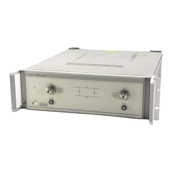
User Manuals: HP 8517B S-Parameter Test Set
Manuals and User Guides for HP 8517B S-Parameter Test Set. We have
1
HP 8517B S-Parameter Test Set manual available for free PDF download: Operating & Service Manual
HP 8517B Operating & Service Manual (136 pages)
S-Parameter Test Set
Brand:
HP
| Category:
Accessories
| Size: 2.12 MB
Table of Contents
Table of Contents
11
Notice
2
Restricted Rights Legend
2
HP 8517B S-Parameter Test Set
3
What You'll Find in this Manual
3
Certification
4
Warranty
4
Assistance
5
Service and Support
6
Instrument Markings
7
Safety and Regulatory Information
7
Before Applying Power
8
Safety Earth Ground
8
Typeface Conventions
9
Table of Contents
11
1 Getting Started
17
How to Use this Manual
17
Test Set Description
18
Figure 1-1. Standard HP 8517B Test Set Block Diagram
18
Figure 1-2. Option 004, HP 8517B Test Set Block Diagram
19
Figure 1-3. Option 007, HP 8517B Test Set Block Diagram
19
HP 8517B Test Set Options
20
Table 1-1. HP 8517B Options and Descriptions
20
Verifying Test Set Operation
21
Table 1-2. Test Set Operation Verification
21
Checking Specifications
21
Checking System Operation
21
Mechanical Specifications
21
Supplemental Characteristics
21
Troubleshooting the Test Set
21
Maintaining Measurement Accuracy
22
Instruments Supported by this Manual
23
Figure 1-4. Instrument Serial-Number Label Example
23
Instrument Firmware Compatibility
24
Service and Support Options Available
25
Accessories
26
Recommended Test Equipment
28
Table 1-6. Recommended Test Equipment
28
Operating and Safety Precautions
29
Safety Precautions
29
2 Installation
31
Initial Inspection
32
Accessories Supplied
32
Operating Environment
32
Storing the Test Set
32
Installing the Test Set into a System Rack
34
Installing the Test Set on a Bench
34
Configuring the Test Set in a System
35
Figure 2-3. Configuring an HP 8517B Test Set in a System
35
And Control Cables
36
Anti-Rotation Clamp
36
Connect System Power
36
Connecting the System Cables
36
Replacing O-Rings in Anti-Rotation Clamps
36
Signal Path Connections
36
Test Port Connectors
36
Packaging the Test Set
37
3 Operating the HP 8517B Test Set
39
Front-Panel Features
39
Figure 3-1. Front-Panel Features of the HP 8517B Test Set
39
Rear-Panel Features
40
Figure 3-2. Rear-Panel Features of the HP 8517B Test Set
40
Controlling Multiple Test Sets
41
Figure 3-3. RF and if Switching with Two Test Sets
42
Table 3-3. RF and if Switch Settings in Figure 3-3, above
42
Multiple Test-Set Connections
43
Initialization at Power-Up
43
Selecting a Test Set
43
RF Switch Driver Control
44
Test Set Addressing
44
Test Set if Switching
44
Figure 3-4. RF and if Switching with Four Test Sets
45
Table 3-5. Coaxial Switch Settings for Figure 3-4, above
45
Measurement Calibration
46
Measuring High-Power Devices with Option 004
47
Changing Signal Path States after System Calibration
48
Changing the Test Port Attenuators
48
Storing Trace Memories
49
Viewing Normalized Parameters
49
Making Operational Checks
51
Performance Verification
52
Using Anti-Rotation Clamps
53
Attach the First Clamp
53
Figure 3-5. Using a Torque Wrench Correctly
54
Positioning the Thumb-Screw
54
Figure 3-6. Visually Aligning Clamp and Nut Flats
55
Figure 3-7. Mating the Clamp and Nut Flats
55
Positioning the Connector
55
Aligning the Thumb-Screw
56
Attaching the Second Clamp
56
Figure 3-8. Aligning the Thumbscrew with the Counter-Sink Hole
56
4 Specifications
58
Mechanical Specifications
58
Supplemental Characteristics
58
5 Troubleshooting the Test Set
61
Theory of Operation
62
Figure 5-1. Standard HP 8517B RF Block Diagram
62
The RF Source Power
62
The Reference Signal Path
63
The S and S Measurements
63
The Sampler Control Switching
63
The Test Signal Path
63
The lo Signal Control
64
Troubleshooting Sequence
65
Figure 5-2. Troubleshooting Flowchart
65
Equipment Needed but Not Supplied
66
Troubleshooting Procedures
67
Table 5-2. Power Supply Voltages to A15
67
Table 5-3. Power Supply Voltages to A27
67
Figure 5-3. Power Supply Fuses and Test Points
68
HP-IB Address Switch
68
Figure 5-4. Instrument HP-IB Switch Setting
69
Fuse Location
69
Board Assembly
69
Figure 5-5. Fuse and Voltage Cam Location
69
Figure 5-6. the ACTIVE LED Location
70
If the Self-Test Fails to Run Properly
70
Table
71
Figure 5-7. HP 8518B Test Set, A4 Board Assembly Leds
71
Table 5-4. Instrument Self-Test Indicator State Definitions
71
Figure 5-8. Service Adapter Connections
72
HP 85102 if Amplifier Test
72
Using the Service Adapter
72
Service Adapter Conclusions
73
Table 5-5. Results Observations
73
Figure 5-9. Diagram of if Signal Path
74
Unratioed Power Test
74
Isolating Signal Path Problems
74
Testing Signal Paths 1-4
74
Testing Paths 5 and 6
76
Figure 5-10. RF Path 1 and Path 2, HP 8517B Standard Test Set
77
Figure 5-11. RF Path 3 and Path 4, HP 8517B Standard Test Set
78
Figure 5-12. RF Path 5 and Path 6, HP 8517B Standard Test Set
79
HP 8517B Option 007
80
HP 8517B Option 007 Test Set
80
HP 8517B, Option 007 Unratioed Power Test
80
Figure 5-15. RF Path 5 and Path 6, HP 8517B Option 007
82
Sample Diagnostics
83
Finding the Faulty Assembly
83
Hp 8517B Test Set Replacement Procedures
85
Figure 6-1. ESD-Safe Workstation Configuration
86
Performance Tests
86
Adjustments
86
Equipment Needed but Not Supplied
87
Figure 6-2. HP 8517B Major Assembly Location Diagram
88
Assembly Replacement Procedures
89
A18 Switch/Splitter Assembly
89
Initial Precautions
89
Switch/Splitter Replacement
89
"A18 Switch/Splitter Assembly
89
A14, A10 to A13 Frequency Converter Assembly
89
Frequency Converter Replacement
89
"A14, A10 to A13 Frequency Converter Assembly
89
A15 Regulator Board Assembly
90
Regulator Board Replacement
90
"A15 Regulator Board Assembly
90
C1 to C4 Filter Capacitors
90
Filter Capacitor Replacement
90
"C1 to C4 Filter Capacitors
90
2.4 MM Test Port Connectors
91
Test Port Connector Replacement
91
Fan Assembly Replacement
92
"Fan Assembly Replacement
92
B1 Fan Assembly
92
Power Transformer Replacement
92
T1 Power Transformer
92
"T1 Power Transformer
92
A1 Front Panel and Interface Board Assembly
94
Front Panel and Interface Board Replacement
94
O-Ring Replacement
94
Anti-Rotation Clamp O-Ring Replacement
94
A16 or A17 Port Attenuators
95
A6 and A8 Test Port Couplers
95
A7 and A9 Bias Tees
95
Bias Tees Replacement
95
Test Port Attenuator Replacement
95
Test Port Coupler Replacement
95
"A1 Front Panel and Interface Board Assembly
95
A22 Input Amplifier Assembly
96
A23 to A26 Buffer Amplifiers
96
Buffer Amplifier Replacement
96
Input Amplifier Replacement
96
A27 Post Regulator Board Assembly
97
Post Regulator Board Replacement
97
7 HP 8517B Replaceable Parts
99
Introduction
99
Rebuilt-Exchange Assemblies
99
Replaceable Parts List
99
Ordering Information
100
Table 7-1. Reference Designation Abbreviations
100
To Order Parts
100
Table 7-2. Manufacturer Names and Addresses
101
Table 7-4. Multipliers, Abbreviation and Description
108
Figure 7-1. Power Cable and Plug Part Numbers
109
Figure 7-2. the Low Cost Rebuilt-Exchange Procedure
111
HP 8517B Test Set
113
HP 8517B Test Set
114
HP 8517B Test Set
115
Table 7-9. Miscellaneous Parts, Front Panel HP 8517B Test Set
117
Table 7-10. Test Port Connector Assembly Components
118
Table 7-11. Miscellaneous Parts, Rear Panel HP 8517B Test Set
119
Figure 7-4. Detailed Views of Hardware Stack-Ups
121
Table 7-18. Parts Unique to Option 002 "Plus" Option 007
131
Advertisement
Advertisement
Related Products
HP 8081A
HP 8691B
HP 8964B
HP 8965B
HP 8692B
HP 8963B
HP 8510p - Notebook PC
HP 8511A
HP 8510
HP 85108A
HP Categories
Desktop
Laptop
Server
Monitor
Switch
More HP Manuals
Login
Sign In
OR
Sign in with Facebook
Sign in with Google
Upload manual
Upload from disk
Upload from URL