Sign In
Upload
Manuals
Brands
D-Link Manuals
Switch
DWS-3024L
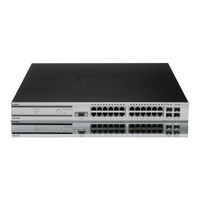
User Manuals: D-Link DWS-3024L Managed Gigabit Switch
Manuals and User Guides for D-Link DWS-3024L Managed Gigabit Switch. We have
2
D-Link DWS-3024L Managed Gigabit Switch manuals available for free PDF download: User Manual
D-link DWS-3024L User Manual (270 pages)
Unified Wired & Wireless Access System
Brand:
D-link
| Category:
Switch
| Size: 11.88 MB
Table of Contents
Table of Contents
3
List of Figures
9
List of Tables
13
About this Document
15
Audience
15
Organization
15
Document Conventions
15
Safety Instructions
16
Safety Cautions
16
Table 1. Typographical Conventions
16
General Precautions for Rack-Mountable Products
18
Protecting against Electrostatic Discharge
19
Battery Handling Reminder
19
1 Overview of the D-Link Unified Access System
21
D-Link Unified Access System Components
21
D-Link Unified Switch
22
D-Link Access Point
22
WLAN Visualization
23
D-Link Unified Access System Topology
23
Figure 1. Sample WLAN Visualization
23
Figure 2. Single Unified Switch with Layer 2 Roaming Support
24
Peer Unified Switch Deployment
24
Single Unified Switch Deployment
24
Understanding the User Interfaces
25
Figure 3. Peer Unified Switch with Layer 3 Roaming Support
25
Figure 4. Web Interface Layout
26
Using the Web Interface
26
Figure 5. Cascading Navigation Menu
27
Figure 6. Hierarchical Tree Navigation Menu
27
Using the Command-Line Interface
28
Using SNMP
29
Wireless System Features and Standards Support
30
2 Planning the D-Link Unified Access System Network
33
System Requirements
33
WLAN Topology Considerations
34
Figure 7. D-Link Unified Access System Components
34
Figure 8. Wiring Closet Topology
35
Access Point Placement
36
Access Point-To-Switch Discovery
36
Figure 9. Data Center Topology
36
Network Planning to Support Layer 3 Roaming
37
Figure 10. Inter-Subnet Roaming
38
3 Installing the Hardware
39
Hardware Overview
39
Front Panel Components
40
Figure 11. Front Panel View of the DWS-3024L as Shipped
40
Figure 12. Front Panel View of the DWS-3024 as Shipped
40
Figure 13. Front Panel View of the DWS-3026 as Shipped
40
LED Indicators
41
Figure 14. LED Indicators on DWS-3024L
41
Figure 15. LED Indicators on DWS-3024
41
Figure 16. LED Indicators on DWS-3026
41
Table 2. LED Description
42
Rear Panel Description
43
Side Panels
43
Figure 17. Rear Panel View of DWS-3024/DWS-3024L
43
Figure 18. Rear Panel View of DWS-3026
43
Installation
44
Package Contents
44
Installation Guidelines
44
Installing the Switch Without the Rack
45
Installing the Switch in a Rack
45
Figure 19. Prepare Switch for Installation on a Desktop or Shelf
45
Figure 20. Fasten Mounting Brackets to Switch
45
Powering on the Switch
46
Installing the SFP Ports
46
Figure 21. Mounting the Switch in a Standard 19" Rack
46
Installing the Optional Modules
47
Figure 22. Inserting the Fiber-Optic Transceivers into the Switch
47
Figure 23. Front Panel of the DEM-410X
48
Figure 24. Front Panel of the DEM-410CX
48
Figure 25. Inserting the Optional Module into the Switch (DWS-3026)
48
Connecting to the External Redundant Power System
49
Connecting the Switch
49
Figure 26. DWS-3026 with Optional DEM-410X Module Installed
49
Figure 27. RPS Connector
49
Connecting the Switch and AP Directly
50
Connecting the Switch to the Network
50
Figure 28. Switch and AP Connected Directly
50
Connecting the Switch and AP through the L2/L3 Network
51
Connecting to the Core Network
51
Figure 29. Switch and Aps Connected through Network
51
Figure 30. Switch Connected to Network Core
51
4 Installing the D-Link Unified Access System
53
System Deployment Overview
53
Connecting the Switch to the Network
55
Enabling the WLAN Features on the Switch
56
Table 3. Basic Wireless Global Configuration
56
Preparing the Access Points
58
Logging on to the AP
58
Figure 31. Ethernet Connection for Static IP Assignment
58
Changing the AP Password
59
Configuring 802.1X Authentication Information on the AP
59
Table 4. IEEE 802.1X Supplicant Commands
59
Configuring AP-To-Switch Authentication Information
60
Configuring VLAN Information on the Access Point
60
Discovering Access Points and Peer Switches
61
Understanding the Discovery Methods
61
Table 5. AP VLAN Commands
61
Figure 32. L2 Discovery Example
62
Figure 33. L3 Discovery Example 1
62
Figure 34. L3 Discovery Example 2
63
Figure 35. DHCP Option Example
63
Discovery and Peer Switches
64
Assigning the IP Address to Switches and Managed Aps
64
Enabling the AP and Peer Switch Discovery
67
Table 6. L3/IP Discovery
70
Authenticating and Validating Access Points
74
Configuring AP Authentication
75
Using the Local Database for AP Validation
76
Figure 36. Requiring AP Authentication
76
Using the RADIUS Database for AP Validation
78
Managing Failed or Rogue Aps
80
5 Configuring Access Point Settings
83
AP Profiles, Networks, and the Local Database
83
Access Point Profiles
83
Networks
84
Local Access Point Database
84
Configuring AAA and RADIUS Settings
85
Table 7. Global RADIUS Server
85
Figure 37. MAC Access Control
86
Configuring Wireless Radio Settings
87
Table 8. MAC Authentication
87
Figure 38. Radio Settings
88
Table 9. Radio Settings
88
Table 10. Advanced Radio Configuration
92
Configuring SSID Settings
93
Managing Virtual Access Point Configuration
93
Figure 39. VAP Settings
93
Configuring the Default Network
94
Table 11. Default VAP Configuration
94
Figure 40. Configuring Network Settings
95
Table 12. Wireless Network Configuration
95
Enabling and Configuring Additional Vaps
98
Figure 41. AP Profile with Five Vaps Enabled
98
Figure 42. Networks Available to the Wireless Client
98
Configuring a VAP for L3 Tunnels
99
Figure 43. L3 Roaming Example
100
Configuring AP Security
101
Figure 44. AP Network Security Options
101
Figure 45. Static WEP Configuration
102
Table 13. Static WEP
102
Figure 46. WPA Personal Configuration
104
Table 14. Static WPA
104
Configuring Valid Access Point Settings
106
Figure 47. Adding a Valid AP
106
Table 15. Valid Access Point Summary
106
Figure 48. Configuring a Valid AP
107
Table 16. Valid AP Configuration
107
Resetting the Access Points
109
Figure 49. Access Point Reset
109
6 Managing and Maintaining D-Link Access Points
109
Managing Radio Frequency Settings
110
Configuring Channel Plan and Power Settings
110
Figure 50. RF Channel Plan and Power Configuration
111
Table 17. RF Channel Plan and Power Adjustment
112
Viewing the Channel Plan History
113
Figure 51. Channel Plan History
113
Initiating Manual Channel Plan Assignments
114
Figure 52. Manual Channel Plan
114
Table 18. Channel Plan History
114
Initiating Manual Power Adjustments
115
Figure 53. Manual Power Adjustments
115
Upgrading the Access Point Software
116
Figure 54. AP Upgrade
116
Table 19. AP Upgrade
116
Figure 55. AP Upgrade Status
117
Table 20. AP Upgrade Status
118
Performing Advanced Access Point Management
119
Figure 56. Advanced AP Management
119
Table 21. Advanced AP Management
119
Adjusting the Channel and Power
120
Enabling AP Debugging
120
Table 22. AP Debug
120
Table 23. Managed AP Channel/Power Adjust
120
7 Monitoring Status and Statistics
123
Monitoring Wireless Global Information
123
Figure 57. Global WLAN Status
124
Table 24. Global WLAN Statistics
124
Viewing IP Discovery Status
126
Monitoring Peer Switch Status
126
Figure 58. Wireless Discovery Status
126
Monitoring All Access Points
127
Figure 59. Peer Switch Status
127
Figure 60. All Access Points
127
Table 25. Peer Switch Status
127
Table 26. Monitoring All Access Points
128
Monitoring Managed Access Point Status
130
Figure 61. Managed AP Status
130
Table 27. Managed Access Point Status
130
Table 28. Detailed Managed Access Point Status
132
Viewing Managed Access Point Radio Summary Information
133
Table 29. Managed AP Radio Summary
134
Table 30. Managed AP Radio Detail
134
Viewing Detailed Managed Access Point Radio Information
134
Viewing Managed Access Point Neighbor Aps
135
Table 31. Managed AP Neighbor Status
136
Viewing Clients Associated with Neighbor Access Points
136
Table 32. Neighbor AP Clients
137
Viewing Managed Access Point Vaps
137
Figure 62. Managed AP Statistics
138
Monitoring Managed AP Statistics
138
Table 33. Managed Access Point VAP Status
138
Table 34. Managed Access Point WLAN Summary Statistics
139
Table 35. Managed Access Point Ethernet Summary Statistics
139
Table 36. Detailed Managed Access Point Statistics
140
Table 37. Managed Access Point Radio Statistics
140
Table 38. Managed Access Point VAP Statistics
141
Viewing Access Point Authentication Failure Status
142
Figure 63. Authentication Failed AP Status
142
Monitoring Rogue and RF Scan Access Points
143
Table 39. Access Point Authentication Failure Status
143
Figure 64. RF Scan
144
Monitoring Associated Client Information
145
Figure 65. Associated Client Status
145
Table 40. Access Point RF Scan Status
145
Table 41. Associated Client Status Summary
146
Viewing Associated Client Status
146
Table 42. Detailed Associated Client Status
147
Table 43. Associated Client Neighbor AP Status
148
Table 44. Associated Client SSID Status
149
Table 45. Associated Client VAP Status
149
Viewing Associated Client SSID Status
149
Viewing Associated Client Statistics
149
Viewing Associated Client VAP Status
149
Table 46. Associated Client Association Summary Statistics
150
Table 47. Associated Client Summary Statistics
150
Table 48. Associated Client Association Detail Statistics
150
Viewing Client Authentication Failure Status
151
Table 49. Associated Client Session Detail Statistics
151
Figure 66. Client Authentication Failure Status
152
Table 50. Failed Client Status
152
Monitoring and Managing Ad Hoc Clients
153
Figure 67. Ad Hoc Clients
153
Table 51. Client Authentication Failure Status
153
Table 52. Ad Hoc Client Status
154
8 Configuring Advanced Settings
155
Creating, Configuring, and Managing AP Profiles
155
Figure 68. Multiple AP Profiles
156
Creating, Copying, and Deleting AP Profiles
157
Figure 69. Adding a Profile
157
Figure 70. Configuring an AP Profile
157
Applying an AP Profile
158
Figure 71. Applying the AP Profile
158
Configuring Global Settings
159
Figure 72. Global Configuration
159
Table 53. General Global Configurations
160
Enabling SNMP Traps
161
Figure 73. SNMP Trap Configuration
161
Table 54. SNMP Traps
161
Configuring Qos
163
Figure 74. Qos Configuration
163
Table 55. Qos Settings
164
9 Configuring the Captive Portal
167
Figure 75. Navigating to the Captive Portal Feature
167
Configuring Global Captive Portal Settings
168
Figure 76. Global Captive Portal Configuration
168
Table 56. Global Captive Portal Configuration
168
Configuring the Captive Portal
169
Figure 77. Captive Portal Summary
169
Table 57. Captive Portal Summary
169
Changing the Captive Portal Settings
170
Figure 78. Captive Portal Configuration
170
Table 58. CP Configuration
170
Customizing the Captive Portal Web Page
172
Figure 79. CP Web Page Customization
172
Table 59. CP Web Page Customization
173
Monitoring and Configuring Captive Portal Users
174
Figure 80. Captive Portal Local User Summary
174
Configuring Users in the Local Database
175
Figure 81. Local User Configuration
175
Table 60. Local User Summary
175
Table 61. Local User Configuration
175
Configuring Users in a Remote RADIUS Server
176
Table 62. Captive Portal User RADIUS Attributes
176
Associating Interfaces with the Captive Portal
177
Figure 82. Global Captive Portal Configuration
177
Table 63. Global Captive Portal Configuration
177
Viewing the Captive Portal Global Status
178
Figure 83. Global Captive Portal Status
178
Figure 84. CP Activation and Activity Status
179
Table 64. Global Captive Portal Status
179
Viewing CP Activation and Activity Status
179
Table 65. CP Activation and Activity Status
180
Figure 85. Interface Activation Status
181
Table 66. Interface Activation Status
181
Viewing Interface Activation Status
181
Viewing Interface Capability Status
181
Figure 86. Interface Capability Status
182
Table 67. Interface and Capability Status
182
Figure 87. Client Summary
183
Table 68. Client Summary
183
Figure 88. Client Detail
184
Table 69. Client Detail
184
Viewing Client Detail
184
Figure 89. Client Statistics
185
Figure 90. Interface - Client Status
185
Table 70. Client Interface Association Connection Statistics
185
Viewing the Client Interface Association Status
185
Viewing the Client Statistics
185
Figure 91. CP - Client Status
186
Table 71. Interface - Client Status
186
Table 72. CP - Client Status
186
Viewing the Client CP Association Status
186
Viewing the Client Summary
183
Figure 92. SNMP Trap Configuration
187
SNMP Trap Configuration
187
Table 73. SNMP Trap Configuration
187
10 Visualizing the Wireless Network
189
Importing and Configuring a Background Image
190
Figure 93. Sample WLAN Visualization
190
Setting up the Graph Components
191
Creating a New Graph
191
Graphing the WLAN Components
194
Figure 94. Multiple Graphs
194
Figure 95. List View and Tabbed View
194
Figure 96. Component Tool Tip
195
Understanding the Menu Bar Options
196
Figure 97. Graphed Components
196
Table 74. WLAN Visualization Menu Bar Options
196
Figure 98. Legend
198
Legend Menu
198
Figure 100. Channel Colors
199
Figure 99. Sentry Mode - Detailed View
199
Figure 101. Tool Tip for Radio Managed AP Information
200
Managing the Graph
201
Figure 102. Wireless Component Attributes
201
Table 75. Component Information
201
A D-Link Unified Access System Default Settings
203
Default D-Link Unified Switch Settings
203
Table 76. Switch Defaults
203
Default D-Link Access Point Settings
204
Table 77. Default AP Settings
204
Default D-Link Access Point Profile Settings
205
Table 78. AP Profile Default Settings
205
Default Captive Portal Settings
206
Table 79. Default Captive Portal Settings
206
B Configuring the External RADIUS Server
207
Configuring RADIUS Settings for Access Points
207
Table 80. RADIUS Attributes for the Access Point
207
Freeradius Server Configuration Example
209
Configuring RADIUS Clients
209
Creating and Including an Attribute Dictionary
209
Adding Access Points to the Valid AP Database
210
Configuring RADIUS Settings for Wireless Clients
211
Configuring RADIUS for Client MAC Authentication
211
Table 81. RADIUS Attributes for Wireless Clients
211
Table 82. RADIUS Attributes for Wireless Client MAC Authentication
211
Freeradius Example for Wireless Client Configuration
212
Configuring User-Based Authentication and Dynamic Vlans
212
Configuring MAC Authentication
213
C L3 Roaming Example
215
Configuring the WLAN and Tunnel Interfaces
216
Figure 103. Example of a Network with L3 Tunnel Subnet
216
Using a Loopback Interface for the Wireless Functions
217
Creating the VLAN Routing Interface
218
Configuring the L3 Tunnel Network
220
Example of Configuring L3 Roaming by Using the CLI
221
Table 83. L3 Tunnel Status Values
223
Example of Configuring L3 Roaming by Using the Web Interface
224
Configuring DHCP Relay and the DHCP Server
225
Configuring the Relay Agent
225
Configuring the DHCP Server
226
D Understanding Quality of Service
229
Qos and Load Balancing
229
802.11E and WMM Standards Support
229
Coordinating Traffic Flow
230
Qos Queues and DSCP on Packets
230
EDCF Control of Data Frames and AIFS
231
Random Backoff and Contention Windows
232
Packet Bursting for Better Performance
232
TXOP Interval for Client Stations
233
802.1P and DSCP Tags
233
Figure 104. Traffic Prioritization
234
Table 84. VLAN Priority Tags
234
E Limited Warranty (USA Only)
235
Product Registration
239
Limited Warranty
240
What You Must Do for Warranty Service
241
What Is Not Covered
241
Trademarks
242
Copyright Statement
242
FCC Warning
242
Technical Support
243
Assistance Technique
246
Pomoc Techniczna
250
International Offices
267
Registration Card All Countries and Regions Excluding USA
268
Advertisement
D-Link DWS-3024L User Manual (268 pages)
Unified Wired & Wireless Access System
Brand:
D-Link
| Category:
Wireless Access Point
| Size: 6.85 MB
Table of Contents
User Manual
1
Table of Contents
3
List of Figures
9
List of Tables
13
About this Document
15
Audience
15
Organization
15
Document Conventions
15
Safety Instructions
16
Safety Cautions
16
Table 1. Typographical Conventions
16
General Precautions for Rack-Mountable Products
18
Protecting against Electrostatic Discharge
19
Battery Handling Reminder
19
1 Overview of the D-Link Unified Access System
21
D-Link Unified Access System Components
21
D-Link Unified Switch
22
D-Link Access Point
22
WLAN Visualization
23
D-Link Unified Access System Topology
23
Figure 1. Sample WLAN Visualization
23
Figure 2. Single Unified Switch with Layer 2 Roaming Support
24
Peer Unified Switch Deployment
24
Single Unified Switch Deployment
24
Understanding the User Interfaces
25
Figure 3. Peer Unified Switch with Layer 3 Roaming Support
25
Figure 4. Web Interface Layout
26
Using the Web Interface
26
Figure 5. Cascading Navigation Menu
27
Figure 6. Hierarchical Tree Navigation Menu
27
Using the Command-Line Interface
28
Using SNMP
29
Wireless System Features and Standards Support
30
2 Planning the D-Link Unified Access System Network
33
System Requirements
33
WLAN Topology Considerations
34
Figure 7. D-Link Unified Access System Components
34
Figure 8. Wiring Closet Topology
35
Access Point Placement
36
Access Point-To-Switch Discovery
36
Figure 9. Data Center Topology
36
Network Planning to Support Layer 3 Roaming
37
Figure 10. Inter-Subnet Roaming
38
3 Installing the Hardware
39
Hardware Overview
39
Front Panel Components
40
Figure 11. Front Panel View of the DWS-3024L as Shipped
40
Figure 12. Front Panel View of the DWS-3024 as Shipped
40
Figure 13. Front Panel View of the DWS-3026 as Shipped
40
LED Indicators
41
Figure 14. LED Indicators on DWS-3024L
41
Figure 15. LED Indicators on DWS-3024
41
Figure 16. LED Indicators on DWS-3026
41
Table 2. LED Description
42
Rear Panel Description
43
Side Panels
43
Figure 17. Rear Panel View of DWS-3024/DWS-3024L
43
Figure 18. Rear Panel View of DWS-3026
43
Installation
44
Package Contents
44
Installation Guidelines
44
Installing the Switch Without the Rack
45
Installing the Switch in a Rack
45
Figure 19. Prepare Switch for Installation on a Desktop or Shelf
45
Figure 20. Fasten Mounting Brackets to Switch
45
Powering on the Switch
46
Installing the SFP Ports
46
Figure 21. Mounting the Switch in a Standard 19" Rack
46
Installing the Optional Modules
47
Figure 22. Inserting the Fiber-Optic Transceivers into the Switch
47
Figure 23. Front Panel of the DEM-410X
48
Figure 24. Front Panel of the DEM-410CX
48
Figure 25. Inserting the Optional Module into the Switch (DWS-3026)
48
Connecting to the External Redundant Power System
49
Connecting the Switch
49
Figure 26. DWS-3026 with Optional DEM-410X Module Installed
49
Figure 27. RPS Connector
49
Connecting the Switch and AP Directly
50
Connecting the Switch to the Network
50
Figure 28. Switch and AP Connected Directly
50
Connecting the Switch and AP through the L2/L3 Network
51
Connecting to the Core Network
51
Figure 29. Switch and Aps Connected through Network
51
Figure 30. Switch Connected to Network Core
51
4 Installing the D-Link Unified Access System
53
System Deployment Overview
53
Connecting the Switch to the Network
55
Enabling the WLAN Features on the Switch
56
Table 3. Basic Wireless Global Configuration
56
Preparing the Access Points
58
Logging on to the AP
58
Figure 31. Ethernet Connection for Static IP Assignment
58
Changing the AP Password
59
Configuring 802.1X Authentication Information on the AP
59
Table 4. IEEE 802.1X Supplicant Commands
59
Configuring AP-To-Switch Authentication Information
60
Configuring VLAN Information on the Access Point
60
Discovering Access Points and Peer Switches
61
Understanding the Discovery Methods
61
Table 5. AP VLAN Commands
61
Figure 32. L2 Discovery Example
62
Figure 33. L3 Discovery Example 1
62
Figure 34. L3 Discovery Example 2
63
Figure 35. DHCP Option Example
63
Discovery and Peer Switches
64
Assigning the IP Address to Switches and Managed Aps
64
Enabling the AP and Peer Switch Discovery
67
Table 6. L3/IP Discovery
70
Authenticating and Validating Access Points
74
Configuring AP Authentication
75
Using the Local Database for AP Validation
76
Figure 36. Requiring AP Authentication
76
Using the RADIUS Database for AP Validation
78
Managing Failed or Rogue Aps
80
5 Configuring Access Point Settings
83
AP Profiles, Networks, and the Local Database
83
Access Point Profiles
83
Networks
84
Local Access Point Database
84
Configuring AAA and RADIUS Settings
85
Table 7. Global RADIUS Server
85
Figure 37. MAC Access Control
86
Configuring Wireless Radio Settings
87
Table 8. MAC Authentication
87
Figure 38. Radio Settings
88
Table 9. Radio Settings
88
Configuring SSID Settings
92
Table 10. Advanced Radio Configuration
92
Figure 39. VAP Settings
93
Managing Virtual Access Point Configuration
93
Configuring the Default Network
94
Table 11. Default VAP Configuration
94
Figure 40. Configuring Network Settings
95
Table 12. Wireless Network Configuration
95
Enabling and Configuring Additional Vaps
98
Figure 41. AP Profile with Five Vaps Enabled
98
Figure 42. Networks Available to the Wireless Client
98
Configuring a VAP for L3 Tunnels
99
Figure 43. L3 Roaming Example
100
Configuring AP Security
101
Figure 44. AP Network Security Options
101
Figure 45. Static WEP Configuration
102
Table 13. Static WEP
102
Figure 46. WPA Personal Configuration
104
Table 14. Static WPA
104
Configuring Valid Access Point Settings
106
Figure 47. Adding a Valid AP
106
Table 15. Valid Access Point Summary
106
Figure 48. Configuring a Valid AP
107
Table 16. Valid AP Configuration
107
6 Managing and Maintaining D-Link Access Points
109
Resetting the Access Points
109
Figure 49. Access Point Reset
109
Managing Radio Frequency Settings
110
Configuring Channel Plan and Power Settings
110
Figure 50. RF Channel Plan and Power Configuration
111
Table 17. RF Channel Plan and Power Adjustment
112
Viewing the Channel Plan History
113
Figure 51. Channel Plan History
113
Initiating Manual Channel Plan Assignments
114
Figure 52. Manual Channel Plan
114
Table 18. Channel Plan History
114
Initiating Manual Power Adjustments
115
Figure 53. Manual Power Adjustments
115
Upgrading the Access Point Software
116
Figure 54. AP Upgrade
116
Table 19. AP Upgrade
116
Figure 55. AP Upgrade Status
117
Performing Advanced Access Point Management
118
Table 20. AP Upgrade Status
118
Enabling AP Debugging
119
Figure 56. Advanced AP Management
119
Table 21. Advanced AP Management
119
Adjusting the Channel and Power
120
Table 22. AP Debug
120
Table 23. Managed AP Channel/Power Adjust
120
7 Monitoring Status and Statistics
123
Monitoring Wireless Global Information
123
Figure 57. Global WLAN Status
124
Table 24. Global WLAN Statistics
124
Viewing IP Discovery Status
126
Monitoring Peer Switch Status
126
Figure 58. Wireless Discovery Status
126
Monitoring All Access Points
127
Figure 59. Peer Switch Status
127
Figure 60. All Access Points
127
Table 25. Peer Switch Status
127
Table 26. Monitoring All Access Points
128
Monitoring Managed Access Point Status
130
Figure 61. Managed AP Status
130
Table 27. Managed Access Point Status
130
Table 28. Detailed Managed Access Point Status
132
Table 29. Managed AP Radio Summary
134
Table 30. Managed AP Radio Detail
134
Table 31. Managed AP Neighbor Status
136
Table 32. Neighbor AP Clients
137
Figure 62. Managed AP Statistics
138
Monitoring Managed AP Statistics
138
Table 33. Managed Access Point VAP Status
138
Table 34. Managed Access Point WLAN Summary Statistics
139
Table 35. Managed Access Point Ethernet Summary Statistics
139
Table 36. Detailed Managed Access Point Statistics
140
Table 37. Managed Access Point Radio Statistics
140
Table 38. Managed Access Point VAP Statistics
141
Viewing Access Point Authentication Failure Status
142
Figure 63. Authentication Failed AP Status
142
Monitoring Rogue and RF Scan Access Points
143
Table 39. Access Point Authentication Failure Status
143
Figure 64. RF Scan
144
Monitoring Associated Client Information
145
Figure 65. Associated Client Status
145
Table 40. Access Point RF Scan Status
145
Table 41. Associated Client Status Summary
146
Viewing Associated Client Status
146
Table 42. Detailed Associated Client Status
147
Table 43. Associated Client Neighbor AP Status
148
Table 44. Associated Client SSID Status
149
Table 45. Associated Client VAP Status
149
Viewing Associated Client SSID Status
149
Viewing Associated Client Statistics
149
Viewing Associated Client VAP Status
149
Table 46. Associated Client Association Summary Statistics
150
Table 47. Associated Client Summary Statistics
150
Table 48. Associated Client Association Detail Statistics
150
Viewing Client Authentication Failure Status
151
Table 49. Associated Client Session Detail Statistics
151
Figure 66. Client Authentication Failure Status
152
Table 50. Failed Client Status
152
Monitoring and Managing Ad Hoc Clients
153
Figure 67. Ad Hoc Clients
153
Table 51. Client Authentication Failure Status
153
Table 52. Ad Hoc Client Status
154
8 Configuring Advanced Settings
155
Creating, Configuring, and Managing AP Profiles
155
Figure 68. Multiple AP Profiles
156
Creating, Copying, and Deleting AP Profiles
157
Figure 69. Adding a Profile
157
Figure 70. Configuring an AP Profile
157
Applying an AP Profile
158
Figure 71. Applying the AP Profile
158
Configuring Global Settings
159
Figure 72. Global Configuration
159
Table 53. General Global Configurations
160
Enabling SNMP Traps
161
Figure 73. SNMP Trap Configuration
161
Table 54. SNMP Traps
161
Configuring Qos
163
Figure 74. Qos Configuration
163
Table 55. Qos Settings
164
9 Configuring the Captive Portal
167
Configuring Global Captive Portal Settings
167
Figure 75. Global Captive Portal Configuration
167
Configuring the Captive Portal
168
Figure 76. Captive Portal Summary
168
Table 56. Global Captive Portal Configuration
168
Table 57. Captive Portal Summary
169
Changing the Captive Portal Settings
170
Figure 77. Captive Portal Configuration
170
Table 58. CP Configuration
171
Monitoring and Configuring Captive Portal Users
172
Figure 78. Captive Portal Local User Summary
173
Table 59. Local User Summary
173
Configuring Users in a Remote RADIUS Server
174
Configuring Users in the Local Database
174
Figure 79. Local User Configuration
174
Table 60. Local User Configuration
174
Associating Interfaces with the Captive Portal
175
Figure 80. Global Captive Portal Configuration
175
Table 61. Captive Portal User RADIUS Attributes
175
Table 62. Global Captive Portal Configuration
176
Viewing the Captive Portal Global Status
177
Figure 81. Global Captive Portal Status
177
Table 63. Global Captive Portal Status
177
Figure 82. CP Activation and Activity Status
178
Table 64. CP Activation and Activity Status
178
Viewing CP Activation and Activity Status
178
Figure 83. Interface Activation Status
179
Viewing Interface Activation Status
179
Table 65. Interface Activation Status
180
Figure 84. Interface Capability Status
181
Table 66. Interface and Capability Status
181
Viewing Interface Capability Status
181
Viewing the Client Summary
182
Figure 85. Client Summary
182
Table 67. Client Summary
182
Figure 86. Client Detail
183
Table 68. Client Detail
183
Viewing Client Detail
183
Figure 87. Client Statistics
184
Figure 88. Interface - Client Status
184
Table 69. Client Interface Association Connection Statistics
184
Viewing the Client Interface Association Status
184
Viewing the Client Statistics
184
Figure 89. CP - Client Status
185
Table 70. Interface - Client Status
185
Table 71. CP - Client Status
185
Viewing the Client CP Association Status
185
SNMP Trap Configuration
186
Figure 90. SNMP Trap Configuration
186
Table 72. SNMP Trap Configuration
186
10 Visualizing the Wireless Network
187
Importing and Configuring a Background Image
188
Figure 91. Sample WLAN Visualization
188
Setting up the Graph Components
189
Creating a New Graph
189
Graphing the WLAN Components
192
Figure 92. Multiple Graphs
192
Figure 93. List View and Tabbed View
192
Figure 94. Component Tool Tip
193
Understanding the Menu Bar Options
194
Figure 95. Graphed Components
194
Table 73. WLAN Visualization Menu Bar Options
194
Figure 96. Legend
196
Legend Menu
196
Figure 97. Sentry Mode - Detailed View
197
Figure 98. Channel Colors
197
Figure 99. Tool Tip for Radio Managed AP Information
198
Managing the Graph
199
Figure 100. Wireless Component Attributes
199
Table 74. Component Information
199
A D-Link Unified Access System Default Settings
201
Default D-Link Unified Switch Settings
201
Table 75. Switch Defaults
201
Default D-Link Access Point Settings
202
Table 76. Default AP Settings
202
Default D-Link Access Point Profile Settings
203
Table 77. AP Profile Default Settings
203
Default Captive Portal Settings
204
Table 78. Default Captive Portal Settings
204
B Configuring the External RADIUS Server
205
Configuring RADIUS Settings for Access Points
205
Table 79. RADIUS Attributes for the Access Point
205
Freeradius Server Configuration Example
207
Configuring RADIUS Clients
207
Creating and Including an Attribute Dictionary
207
Adding Access Points to the Valid AP Database
208
Configuring RADIUS Settings for Wireless Clients
209
Configuring RADIUS for Client MAC Authentication
209
Table 80. RADIUS Attributes for Wireless Clients
209
Table 81. RADIUS Attributes for Wireless Client MAC Authentication
209
Freeradius Example for Wireless Client Configuration
210
Configuring User-Based Authentication and Dynamic Vlans
210
Configuring MAC Authentication
211
C L3 Roaming Example
213
Configuring the WLAN and Tunnel Interfaces
214
Figure 101. Example of a Network with L3 Tunnel Subnet
214
Using a Loopback Interface for the Wireless Functions
215
Creating the VLAN Routing Interface
216
Configuring the L3 Tunnel Network
219
Example of Configuring L3 Roaming by Using the CLI
219
Table 82. L3 Tunnel Status Values
221
Example of Configuring L3 Roaming by Using the Web Interface
222
Configuring DHCP Relay and the DHCP Server
223
Configuring the Relay Agent
223
Configuring the DHCP Server
224
D Understanding Quality of Service
227
Qos and Load Balancing
227
802.11E and WMM Standards Support
227
Coordinating Traffic Flow
228
Qos Queues and DSCP on Packets
228
EDCF Control of Data Frames and AIFS
229
Random Backoff and Contention Windows
230
Packet Bursting for Better Performance
230
TXOP Interval for Client Stations
231
802.1P and DSCP Tags
231
Figure 102. Traffic Prioritization
232
Table 83. VLAN Priority Tags
232
E Limited Warranty (USA Only)
233
Product Registration
237
Limited Warranty
238
What You Must Do for Warranty Service
239
What Is Not Covered
239
Trademarks
240
Copyright Statement
240
FCC Warning
240
Technical Support
241
Assistance Technique
244
International Offices
265
Registration Card All Countries and Regions Excluding USA
266
Advertisement
Related Products
D-link DWS-3024
D-Link UNIFIED WIRED & WIRELESS ACCESS SYSTEM DWS-3000
D-Link DWS-3024 - L2+ Gigabit Wireless Switch
D-Link DWS-3026 - L2+ Gigabit Wireless Switch
D-Link DWS-3026
D-link DWS-3250 - xStack Switch - Stackable
D-Link DWS-3160-24PC
D-Link xStack DWS-3200 Series
D-Link DWS-3160 Series
D-Link DWS-3227P-TAA - 24GIGABIT Wireless Switch
D-Link Categories
Network Router
Switch
Wireless Router
Adapter
Security Camera
More D-Link Manuals
Login
Sign In
OR
Sign in with Facebook
Sign in with Google
Upload manual
Upload from disk
Upload from URL