Sign In
Upload
Manuals
Brands
Canon Manuals
All in One Printer
MF8100 Series
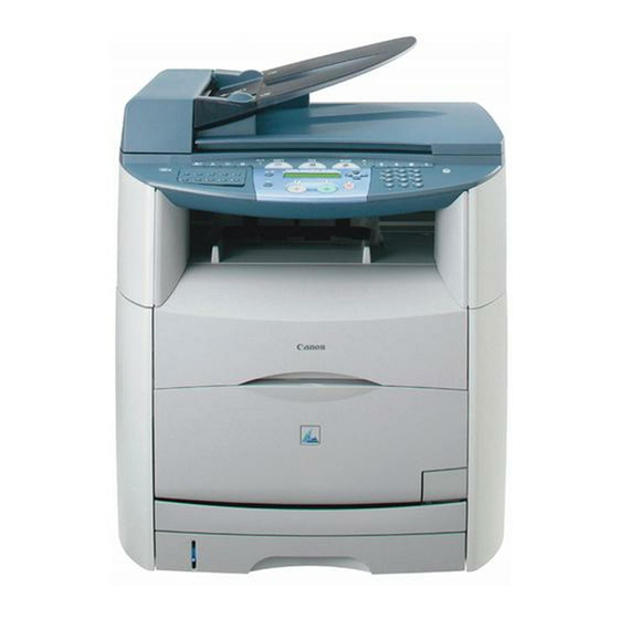
User Manuals: Canon MF8100 Series Multifunction Printer
Manuals and User Guides for Canon MF8100 Series Multifunction Printer. We have
1
Canon MF8100 Series Multifunction Printer manual available for free PDF download: Service Manual
Canon MF8100 Series Service Manual (296 pages)
MF8100 Series
Brand:
Canon
| Category:
All in One Printer
| Size: 15.62 MB
Table of Contents
Table of Contents
7
Service Manual
1
Chapter 1 PRODUCT DESCRIPTION
21
Product Specifications
25
Names of Parts
27
External View
27
Cross Sectional View
28
Major Unit
28
Major Component
29
Safety
29
Points to Note When Replacing/Disposing of the Lithium Battery
29
Safety and Ozone
29
Safety of the Laser Light
29
Safety of Toner
29
CDRH Ordinances
30
Functional Configuration
30
Functional Construction
30
Basic Sequense
30
Basic Operation Sequence
30
Power-On Sequence
31
Chapter 2 TECHNICAL REFERENCE
33
Table of Contents
35
Document Feed and Exposure System
37
Major Components
37
Overview
37
Overview/Configuration
37
Basic Sequence
38
Basic Sequence of Operation at Power-On
38
Basic Sequence of Operation in Response to a Press on the Start Key (Book)
39
Laser Exposure
40
Outline
40
Overview/Configuration
40
Controlling the Laser
41
Laser Emission Control
41
Outline
41
Automatic Power Control (APC)
42
Horizontal Synchronous Control
42
Image Mask Control
42
Laser Emission Control
42
Laser Failure Detection
42
Controlling the Laser Scanner Motor
43
Outline
43
Scanner Motor Failure Detection
43
Scanner Motor Speed Control
43
Image Formation
43
Overview/Configuration
43
Electrostatic Latent Image Formation Block
44
Image Formation Process
44
Developing Block
45
Electrostatic Latent Image Formation Block
45
Transfer Block
46
Fixing Block
47
ITB Cleaning Block
48
Developing Bias Generation
50
Driving and Controlling the High-Voltage System
50
Outline
50
Primary Charging Bias Generation
50
Primary Transfer Bias Generation
50
Auxiliary ITB Cleaning Bias Generation
51
Fixing Bias Generation
51
Image Stabilizaton Control
51
ITB Cleaning Bias Generation
51
Outline
51
Secondary Transfer Bias Generation
51
Developing Rotary
52
Developing Rotary Rotation Control
52
Image Density Calibration (D-Max) Control
52
Image Halftone Calibration (D-Half) Control
52
Outline
52
Developing Rotary Engaging Control
53
Developing Rotary Position Detection
54
Memory Tag
55
Memory Tag Contact Engaging Control
55
Outline
55
Toner Cartridge
55
Cartridge Presence Detection
56
Toner Cartridge Life Detection
56
Drum Cartridge
57
Outline
57
Cleaning Roller Engaging Control
58
Memory Tag
59
Detecting the ITB Home Position
60
Drum Cartridge Presence Detection
61
Checking the Life of the Drum Cartridge
62
Outline
63
Secondary Transfer Mechanism
63
Secondary Transfer Roller Engaging Control
64
Secondary Roller Position Detection
65
Pickup and Feed System
66
Overview
66
Overview/Configuration
66
Pickup/Feeding Assembly
67
Detecting the Machine Inside Temperature
68
Feed Speed Control
68
Other Control
68
Skew Correction Function
68
Delay Jams
69
Delivery Delay Jam
69
Delivery Stationary Jam
69
Detection Jams
69
Jam Detection Outline
69
Other Jams
69
Outline
69
Pick-Up Stationary Jam
69
Pickup Delay Jam
69
Stationary Jams
69
Cassette Pickup Unit
70
Manual Feed Pickup Unit
70
Multi-Purpose Tray Pick-Up
70
Pickup from the Cassette
70
Fixing Unit
70
Outline
70
Overview/Configuration
70
Controlling the Temperature of the Fixing Unit
71
Flicker Prevention Function
71
Heater Temperature Control
71
Protection Function
71
Protective Function
71
Various Control Mechanisms
71
Fixing Unit Failure Detection
72
Engine Control System
72
Construction
72
Overview
72
DC Controller (DCNT)
73
Operations
73
Outline
73
Controlling the Motors and Fans
74
Main Motor Control
74
Developing Rotary Motor Control
75
Cooling Fan
76
Canon Advanced Printing Technologyå@(CARPS)
77
Outline
77
System Controller (SCNT)
77
Chapter 3 DISASSEMBLY and ASSEMBLY
79
Cartridge Removal at Trouble Eruption Cartridge Removal at Trouble Eruption
81
Laser Exposure System
85
Image Formation System
85
Pickup and Feeding System
87
Fixing System
89
Cartridge Removal at Trouble Eruption Cartridge Removal at Trouble Eruption
91
Cartridge Removal at Trouble Eruption
91
Toner Cartridge Removal
91
Drum Cartridge Removal
92
External and Controls System
92
Front Cover
92
Removing the Cassettes
92
Removing the Rear Cover
92
Removing the Right Cover (with the Reader Assembly Intact)
92
Removing the Left Cover (with the Reader Assembly Intact)
93
Removing the
94
Removing the Lower
94
Rear Cover
94
Removing the Rear Cover
94
Top Cover
95
Removing the Cassettes
95
Removing the Reader Assembly
95
Removing the Rear Cover
95
Removing the Face-Down Cover
96
Removing the Left Cover
96
Removing the Power Supply Assembly
96
Removing the Right Cover
96
Removing the Top Cover
97
Right Cover
98
Removing the Cassettes
98
Removing the Rear Cover
98
Removing the Right Cover (with the Reader Assembly Intact)
98
Left Cover
99
Removing the Cassettes
99
Removing the Left Cover (with the Reader Assembly Intact)
99
Removing the Rear Cover
99
Upper Right Cover
100
Removing the Reader Assembly
100
Removing the Rear Cover
100
Removing the Scanner Unit
101
Removing the Upper Right Cover
101
Upper Left Cover
101
Removing the Rear Cover
101
Removing the Reader Assembly
102
Removing the Scanner Unit
103
Removing the Upper Left Cover
103
Face-Up Cover
103
Removing the Fixing Assembly
103
Removing the Face-Up Cover
103
Main Drive Unit
103
Removing the Rear Cover
103
Removing the Reader Assembly
104
Removing the Right Cover
105
Removing the Left Cover
105
Removing the Power Supply Assembly
105
Removing the Face-Down Cover
105
Removing the Top Cover
105
Removing the Right Frame
107
Removing the Inside Cover
107
Removing the Shield Plate
107
Removing the Registration Clutch
107
Removing the Main Drive Assembly
107
Operation Panel Unit
108
Removing the Rear Cover
108
Removing the Scanner Unit
108
Removing the Operation Panel
108
SCNT Board
109
Removing the Rear Cover
109
Removing the Scanner Unit
109
Removing the Board Unit
109
Removing the SCNT Unit
110
DCNT Board
111
Removing the Rear Cover
111
Removing the Reader Assembly
112
Removing the Right Cover
112
Removing the Left Cover
113
Removing the Power Supply Assembly
113
Removing the Face-Down Cover
113
Removing the Top Cover
113
Removing the Right Frame
114
Removing the Shield Plate
114
Removing the DCNT Board
115
NCU Board
115
Removing the Rear Cover
115
Removing the Scanner Unit
115
Removing the Modular Board Cover
116
Removing the NCU Board
116
Modular Board
116
Removing the Rear Cover
116
Removing the Scanner Unit
116
Removing the Modular PCB
117
Removing the Modular Board Cover
117
Power Supply PCB
117
Removing the Rear Cover
117
Removing the Reader Assembly
117
Removing the Power Supply Assembly
118
Removing the Power Supply PCB
118
Print Power Supply PCB
119
Removing the Fixing Assembly
119
Removing the Rear Cover
119
Removing the Reader Assembly
119
Removing the Right Cover
120
Removing the Left Cover
120
Removing the Power Supply Assembly
120
Removing the Face-Down Cover
121
Removing the Top Cover
121
Removing the Right Frame
122
Removing the Left Frame
122
Removing the Cassette Feeder
122
Removing the Fan Duct
122
Removing the Shield Plate
122
Removing the Lower Case Assembly
123
Removing the Printer Power Supply PCB
123
High-Voitage Power Supply PCB
123
Removing the Fixing Assembly
123
Removing the Reader Assembly
124
Removing the Rear Cover
124
Removing the Left Cover
125
Removing the Power Supply Assembly
125
Removing the Right Cover
125
Removing the Face-Down Cover
126
Removing the Top Cover
126
Removing the Cassette Feeder
127
Removing the Fan Duct
127
Removing the Left Frame
127
Removing the Right Frame
127
Removing the Shield Plate
127
Removing the High-Voltage Power Supply PCB
128
Removing the Lower Case Assembly
128
Removing the Sub High-Voltage Power Supply PCB Unit
128
Sub High-Voltage Power Supply PCB
128
Removing the Fixing Assembly
128
Removing the Reader Assembly
129
Removing the Rear Cover
129
Removing the Left Cover
130
Removing the Power Supply Assembly
130
Removing the Right Cover
130
Removing the Face-Down Cover
131
Removing the Top Cover
131
Removing the Cassette Feeder
132
Removing the Fan Duct
132
Removing the Left Frame
132
Removing the Right Frame
132
Removing the Shield Plate
132
Removing the Lower Case Assembly
133
Removing the Sub High-Voltage Power Supply Board
133
Internal Temperature Detection Thermistor
133
Removing the Rear Cover
133
Removing the Reader Assembly
134
Removing the Right Cover
134
Removing the Face-Down Cover
135
Removing the Left Cover
135
Removing the Power Supply Assembly
135
Removing the Top Cover
135
Removing the Right Frame
136
Removing the Shield Plate
136
Removing the Machine Inside Temperature Thermistor
137
Cooling Fan
137
Removing the Reader Assembly
137
Removing the Rear Cover
137
Removing the Left Cover
138
Removing the Right Cover
138
Removing the Face-Down Cover
139
Removing the Power Supply Assembly
139
Removing the Top Cover
139
Removing the Cooling Fan
140
Removing the Fan Duct
140
Removing the Left Frame
140
ADF Unit
141
Removing the Scanner Unit
142
Removing the SCNT Board Unit
142
Removing the ADF Unit
142
Points to Note When Mounting the ADF Unit
143
Document Feed/Exposure System
141
Scanner Unit
141
Removing the Rear Cover
141
Removing the Scanner Unit
141
Scanner Cover Unit
143
Removing the Rear Cover
143
Removing the Scanner Unit
143
Removing the SCNT Board Unit
144
Removing the ADF Unit
144
Removing the Operation Panel
144
Removing the Scanner Cover Unit
145
CCD Unit
145
Removing the Rear Cover
145
Removing the Scanner Unit
145
Removing the NCU Board
146
Removing the SCNT Board Unit
146
Removing the ADF Unit
146
Removing the Operation Panel
147
Removing the Scanner Cover Unit
147
Removing the Flat Bed Motor Unit
147
Removing the CCD Unit
147
Separation Guide Unit
147
Removing the Rear Cover
147
Removing the Scanner Unit
148
Removing the SCNT Board Unit
148
Removing the ADF Unit
148
Points to Note When Mounting the ADF Unit
149
Removing the Document Pickup Roller Unit
149
Removing the Separation Guide Unit
150
Feed Roller
150
Removing the Rear Cover
150
Removing the Scanner Unit
150
Removing the SCNT Board Unit
151
Removing the ADF Unit
151
Points to Note When Mounting the ADF Unit
151
Removing the Document Feed Roller
151
Pickup Roller Unit
153
Removing the Rear Cover
153
Removing the Scanner Unit
153
Removing the SCNT Board Unit
153
Removing the ADF Unit
154
Points to Note When Mounting the ADF Unit
154
Removing the Document Pickup Roller Unit
154
Reader Unit
155
Removing the Rear Cover
155
Removing the Reader Assembly
155
Flatbed Motor Unit
156
Removing the Rear Cover
156
Removing the Scanner Unit
157
Removing the SCNT Board Unit
157
Removing the ADF Unit
157
Removing the Operation Panel
158
Removing the Scanner Cover Unit
158
Removing the Flat Bed Motor Unit
158
Document Feed Motor
158
Removing the Rear Cover
158
Removing the Scanner Unit
159
Removing the SCNT Board Unit
159
Points to Note When Mounting the ADF Unit
160
Removing the Document Feed Motor
160
DS Sensor
160
Removing the ADF Paper Sensor
160
DES Sensor
161
Removing the ADF Feed Sensor
161
Speaker
161
Removing the Rear Cover
161
Laser Exposure System
162
Removing the SCNT Board Unit
162
Removing the Speaker
162
Laser/Scanner Unit
162
Removing the Rear Cover
162
Removing the Reader Assembly
163
Removing the Face-Down Cover
164
Removing the Left Cover
164
Removing the Power Supply Assembly
164
Removing the Right Cover
164
Removing the Top Cover
164
Removing the Laser Scanner Unit
166
Image Formation System
166
Rotary Drive Unit
166
Removing the Rear Cover
166
Removing the Reader Assembly
166
Removing the Left Cover
167
Removing the Right Cover
167
Removing the Face-Down Cover
168
Removing the Power Supply Assembly
168
Removing the Top Cover
168
Removing the Right Frame
169
Removing the Rotary Drive Assembly
169
Removing the Shield Plate
169
Drum Cartridge Memory Tag Contact
170
Removing the Reader Assembly
170
Removing the Rear Cover
170
Removing the Left Cover
171
Removing the Right Cover
171
Removing the Face-Down Cover
172
Removing the Power Supply Assembly
172
Removing the Top Cover
172
Removing the Inside Cover
173
Removing the Right Frame
173
Removing the Shield Plate
173
Removing the Drum Cartridge Memory Tag Contact
174
Developing Rotary Unit
174
Removing the Reader Assembly
174
Removing the Rear Cover
174
Removing the Left Cover
175
Removing the Right Cover
175
Removing the Face-Down Cover
176
Removing the Power Supply Assembly
176
Removing the Top Cover
176
Removing the Inside Cover
177
Removing the Right Frame
177
Removing the Shield Plate
177
Removing the Main Drive Assembly
178
Removing the Registration Clutch
178
Removing the Rotary Drive Assembly
178
Removing the Developing Rotary Assembly
179
Removing the Fan Duct
179
Removing the Laser Scanner Unit Base
179
Removing the Left Frame
179
Engaging Motor
180
Removing the Rear Cover
180
Removing the Reader Assembly
180
Removing the Right Cover
181
Removing the Left Cover
181
Removing the Power Supply Assembly
182
Removing the Face-Down Cover
182
Removing the Top Cover
182
Removing the Shift Motor
183
Removing the Left Frame
183
Developing Rotary Motor
183
Removing the Rear Cover
183
Removing the Reader Assembly
184
Removing the Face-Down Cover
185
Removing the Left Cover
185
Removing the Power Supply Assembly
185
Removing the Right Cover
185
Removing the Top Cover
185
Removing the Developing Rotary Motor
187
Removing the Right Frame
187
Removing the Rotary Drive Assembly
187
Removing the Shield Plate
187
Developing Rotary Stopper Solenoid
187
Removing the Rear Cover
187
Removing the Reader Assembly
188
Removing the Face-Down Cover
189
Removing the Left Cover
189
Removing the Power Supply Assembly
189
Removing the Right Cover
189
Removing the Top Cover
189
Removing the Developing Rotary Motor
191
Removing the Right Frame
191
Removing the Rotary Drive Assembly
191
Removing the Shield Plate
191
Removing the Toner Cartridge Motor
191
Removing the Developing Rotary Stopper Solenoid
192
Density Detection PCB
192
Removing the Rear Cover
192
Removing the Reader Assembly
192
Removing the Left Cover
193
Removing the Right Cover
193
Removing the Face-Down Cover
194
Removing the Power Supply Assembly
194
Removing the Top Cover
194
Removing the Dust-Blocking Cover
195
Removing the Inside Cover
195
Removing the Density Detection PCB
195
ITB Home Position Detection PCB
196
Removing the Rear Cover
196
Removing the Reader Assembly
196
Removing the Right Cover
197
Removing the Left Cover
197
Removing the Power Supply Assembly
197
Removing the Face-Down Cover
197
Removing the Top Cover
198
Removing the ITB Home Position Detection PCB
199
Removing the Inside Cover
199
Transfer Charging Roller
199
Removing the Transfer Charging Roller
199
Waste Toner Detection PCB
200
Removing the Rear Cover
200
Removing the Reader Assembly
200
Removing the Left Cover
201
Removing the Power Supply Assembly
201
Removing the Right Cover
201
Removing the Face-Down Cover
202
Removing the Top Cover
202
Removing the Main Drive Assembly
203
Removing the Registration Clutch
203
Removing the Right Frame
203
Removing the Waste Toner Detection PCB
204
Developing Rotary/Toner Level Detection PCB
204
Removing the Reader Assembly
204
Removing the Rear Cover
204
Removing the Left Cover
205
Removing the Right Cover
205
Removing the Face-Down Cover
206
Removing the Power Supply Assembly
206
Removing the Top Cover
206
Removing the Main Drive Assembly
207
Removing the Registration Clutch
207
Removing the Right Frame
207
Removing the Rotary Drive Assembly
208
Removing the Developing Rotary Assembly
209
Removing the Fan Duct
209
Removing the Laser Scanner Unit Base
209
Removing the Left Frame
209
Removing the Developing Rotary/Toner Level Detection PCB
210
Toner Cartridge Motor
210
Removing the Rear Cover
210
Removing the Left Cover
211
Removing the Reader Assembly
211
Removing the Right Cover
211
Removing the Power Supply Assembly
212
Removing the Face-Down Cover
212
Removing the Top Cover
212
Removing the Right Frame
213
Removing the Rotary Drive Assembly
213
Removing the Shield Plate
213
Pickup and Feeding System
214
Removing the Toner Cartridge Motor
214
Cassette Pickup Roller
214
Removing the Cassettes
214
Removing the Rear Cover
214
Removing the Right Cover
214
Removing the Cassette Pickup Roller
215
Removing the Left Cover
215
Cassette Paper Sensor
215
Removing the Cassettes
215
Removing the Rear Cover
215
Removing the Reader Assembly
216
Removing the Face-Down Cover
217
Removing the Left Cover
217
Removing the Power Supply Assembly
217
Removing the Right Cover
217
Removing the Top Cover
217
Removing the Cassette Paper Sensor
219
Removing the Cassette Feeder
219
Removing the Left Frame
219
Removing the Right Frame
219
Cassette Feed Sensor
219
Removing the Cassettes
219
Removing the Rear Cover
219
Removing the Reader Assembly
220
Removing the Face-Down Cover
221
Removing the Left Cover
221
Removing the Power Supply Assembly
221
Removing the Right Cover
221
Removing the Top Cover
221
Removing the Cassette Feed Sensor
223
Removing the Left Frame
223
Removing the Right Frame
223
Removing the Cassette Feeder
223
Cassette Pickup Solenoid
224
Removing the Cassettes
224
Removing the Reader Assembly
224
Removing the Rear Cover
224
Removing the Face-Down Cover
225
Removing the Left Cover
225
Removing the Power Supply Assembly
225
Removing the Right Cover
225
Removing the Top Cover
226
Removing the Cassette Pickup Solenoid
227
Removing the Cassette Feeder
227
Removing the Left Frame
227
Removing the Right Frame
227
Cassette Separation Pad
227
Removing the Front of the Cassette
227
Removing the Cassette Separation Pad
228
Manual Pickup Roller
228
Removing the Manual Pickup Roller
228
Manual Pickup Solenoid
228
Removing the Rear Cover
228
Removing the Reader Assembly
229
Removing the Face-Down Cover
230
Removing the Left Cover
230
Removing the Power Supply Assembly
230
Removing the Right Cover
230
Removing the Top Cover
230
Removing the Inside Cover
232
Removing the Main Drive Assembly
232
Removing the Registration Clutch
232
Removing the Right Frame
232
Removing the Shield Plate
232
Removing the Manual Pickup Feed Solenoid
233
Manual Separation Roller
233
Removing the Cassettes
233
Removing the Rear Cover
233
Removing the Right Cover (with the Reader Assembly Intact)
233
Removing the Left Cover (with the Reader Assembly Intact)
234
Removing the Front Cover
235
Removing the Lower Front Cover
235
Removing the Manual Feed Pickup Separation Pad
235
Registration Detection PCB
235
Removing the Fixing Assembly
235
Removing the Fixing Assembly
236
Removing the Reader Assembly
236
Removing the Rear Cover
236
Removing the Left Cover
237
Removing the Right Cover
237
Removing the Face-Down Cover
238
Removing the Power Supply Assembly
238
Removing the Top Cover
238
Removing the Cassette Feeder
239
Removing the Left Frame
239
Removing the Right Frame
239
Removing the Fan Duct
240
Removing the Lower Case Assembly
240
Removing the Registration Detection PCB
240
Removing the Shield Plate
240
Main Motor
241
Removing the Reader Assembly
241
Removing the Rear Cover
241
Removing the Face-Down Cover
242
Removing the Left Cover
242
Removing the Power Supply Assembly
242
Removing the Top Cover
243
Removing the Inside Cover
244
Removing the Main Drive Assembly
244
Removing the Registration Clutch
244
Removing the Right Frame
244
Removing the Shield Plate
244
Fixing System
245
Fixing Unit
245
Removing the Fixing Assembly
245
Removing the Main Motor
245
Removing the Right Cover
242
Fixing Film Unit
245
Removing the Face-Up Cover
245
Removing the Fixing Film Unit
246
Fixing Pressure Roller
247
Removing the Face-Up Cover
247
Removing the Fixing Film Unit
247
Removing the Fixing Pressure Roller
249
Removing the Fixing Assembly
247
Fixing Delivery Paper Sensor
249
Pre-Fixing Paper Detection Sensor
249
Removing the Face-Up Cover
249
Removing the Fixing Assembly
249
Removing the Rear Cover
249
Removing the Reader Assembly
250
Removing the Face-Down Cover
251
Removing the Left Cover
251
Removing the Power Supply Assembly
251
Removing the Right Cover
251
Removing the Top Cover
251
Removing the Cassette Feeder
253
Removing the Inside Cover
253
Removing the Left Frame
253
Removing the Registration Clutch
253
Removing the Right Frame
253
Removing the Shield Plate
253
Removing the Fan Duct
254
Removing the Fixing Front Paper Sensor Spacer
254
Removing the Main Drive Assembly
254
Removing the Toner Tray
254
Removing the Fixing Front Paper Sensor
255
Removing the Lower Case Assembly
255
Fixing Motor
255
Removing the Rear Cover
255
Removing the Reader Assembly
256
Removing the Face-Down Cover
257
Removing the Left Cover
257
Removing the Power Supply Assembly
257
Removing the Right Cover
257
Removing the Top Cover
257
Removing the Fixing Motor
259
Removing the Right Frame
259
Removing the Shield Plate
259
User Maintenance/Cleaning the Scanning Area
263
Chapter 4 MAINTENANCE and INSPECTION
263
User Maintenance
263
Cleaning the Scanning Area
263
Mylar Sheet
263
Cleaning the ADF Area
265
Cleaning the Scanning Area
265
Drum Cartridge
265
Mylar Sheet
265
Pressure Roller (Fixing Assembly)
265
Toner Cartridge
265
User Maintenance
265
Consumables
266
Density Sensor/Itb Home Position Sensor
266
Expected Service Life of Consumable Parts
266
Periodic Replacement Parts
266
Periodically Replaced Parts
266
Periodic Service
267
Periodical Service
267
Table of Contents
271
Measurement and Adjustment
273
Electrical Adjustment
273
Initial Check
273
Initial Checkup
273
Test Print
273
Test Printing
273
Work after Replacing the Laser/Scanner Unit
273
Checking the Nip Width of the Lower Fixing Roller
274
Fixing System
274
When Replacing the SCNT Board
274
Service Tools
274
Standard Tools
274
Solvent/Oil List
275
Special Tools
275
Location of Convectors
275
Error Code Outline
277
Service Error Code
277
Hardware Switches
278
Outline
278
Service Data Setting
278
Service Mode
278
Details of Bit 0 and Bit 1
279
Explanation of # SSSW
279
Outline
279
Service Data Entry Method
279
Service Soft Switch Settings (SSSW)
279
Sssw-Sw14
279
Clear
280
Data Initialization Mode (CLEAR)
280
Details of Bit 0
280
Details of Bit 1
280
DRAM Test
280
List of Functions
280
Overview
280
Sssw-Sw18
280
Test Mode (TEST)
280
Test Mode Overview
280
Modem Test
281
Modem Tests
281
Print Test
281
Frequency Test
282
G3 Signal Transmission Test
282
Faculty Test
283
FACULTY Tests
283
Sensor Tests
283
Operation Panel Tests
284
Cluth/Solenid
291
Cluth/Solenoid
291
Motor/Fan
291
Outline of Electrical Components
291
Sensor
292
Switch
292
Switch/Speaker/Thermistor
292
Pcbs
293
Variable Resistors (VR), Test Pins, Jumpers, and Switches
293
Variable Resistors(VR), LED, and Check Pins by PCB
293
Chapter 5 TROUBLESHOOTING
278
Advertisement
Advertisement
Related Products
Canon Color imageCLASS MF8170c
Canon imageclass mf810cdn
Canon imageCLASS MF8380Cdw
Canon Color imageCLASS MF8050Cn
Canon Color imageCLASS MF8350Cdn
Canon Color imageCLASS MF8280Cw
Canon ImageClass MF8580 Cdw
Canon MF8540CD
Canon imageclass mf820cdn
Canon i-SENSYS MF842Cdw
Canon Categories
Printer
Digital Camera
All in One Printer
Camcorder
Scanner
More Canon Manuals
Login
Sign In
OR
Sign in with Facebook
Sign in with Google
Upload manual
Upload from disk
Upload from URL