Sign In
Upload
Manuals
Brands
Canon Manuals
Printer
LBP3150 Series
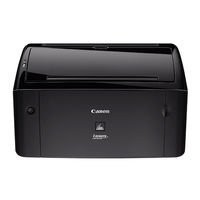
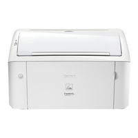
Canon LBP3150 Series Manuals
Manuals and User Guides for Canon LBP3150 Series. We have
2
Canon LBP3150 Series manuals available for free PDF download: Service Manual
Canon LBP3150 Series Service Manual (146 pages)
Brand:
Canon
| Category:
Printer
| Size: 5.7 MB
Table of Contents
Service Manual
1
Symbols Used
4
Table of Contents
7
Chapter 1 PRODUCT DESCRIPTION
13
Features
17
Features
18
Product Specifications
19
Specifications
19
Name of Parts
20
External View
20
Cross Section
21
External View
22
Cross Section
23
Using the Machine
24
Control Panel
24
Safety
24
Safety of Laser Light
24
CDRH Regulations
25
Safety of Toner
25
Handling the Laser Unit
25
Points to Note at Disassembly/Assembly Work
26
Safety of Laser Light
26
CDRH Regulations
26
Safety of Toner
26
Handling the Laser Unit
27
Points to Note at Disassembly/Assembly Work
27
Chapter 2 TECHNICAL REFERENCE
29
Functional Configuration
33
Outline
33
Basic Sequence
33
Basic Sequence of Operation
33
Power-On Sequence
34
Basic Sequence of Operation
34
Laser Exposure System
35
Overview/Configuration
35
Overview
35
Controlling the Laser Activation Timing
36
Laser ON/OFF Control
36
Horizontal Sync Control
37
Laser ON/OFF Control
38
Horizontal Sync Control
38
Laser Control
39
Auto Power Control (APC)
39
Laser Scanner Motor Control
39
Overview
39
Scanner Motor Fault Detection
40
Overview
41
Scanner Motor Fault Detection
41
Image Formation System
42
Overview/Configuration
42
Overview
42
Print Process
42
Static Latent Image Formation Block
43
Development Block
44
Transfer Block
44
Fixing Block
45
Drum Cleaning Block
45
Overview
46
Print Process
46
Static Latent Image Formation Block
47
Development Block
48
Transfer Block
49
Fixing Block
49
Drum Cleaning Block
50
High-Voltage Control
50
Overview
50
Generating Primary Charging Bias
51
Generating Developing Bias
51
Generating Transfer Bias
51
Overview
51
Generating Primary Charging Bias
52
Generating Developing Bias
52
Generating Transfer Bias
52
Toner Cartridge
52
Toner Level Detection
52
Toner Cartridge Absence/Presence Detection
52
Toner Level Detection
54
Toner Cartridge Absence/Presence Detection
54
Pickup and Feeding System
55
Overview/Configuration
55
Overview
55
Detecting Jams
56
Jam Detection Outline
56
Overview
56
Delay Jams
58
Stationary Jams
58
Other Jams
58
Delivery Delay Jam
58
Pickup Stationary Jam
58
Delivery Stationary Jam
58
Fixing Take-Up Jam
58
Remaining Jam at Start-Up
58
External and Controls System
59
Power Supply
59
Low Voltage Power Circuit
59
Low Voltage Power Circuit
60
Protective Functions
61
Power Protective Function
61
Engine Control System
62
Main Controller
62
General Description
62
Safety Function
62
Power Protective Function
62
Engine Controller
63
General Description
63
Fixing Unit/Delivery System
66
Overview/Configuration
66
Overview
66
Main Parts of Fixing Unit
66
Overview
67
Main Parts of Fixing Unit
67
Various Control Mechanisms
68
Fixing Temperature Control
68
Fixing Temperature Control
70
Protective Functions
71
Protective Function of Fixing Unit
71
Error Detection
71
Other Functions
72
Throughput down Control
72
Chapter 3 DISASSEMBLY and ASSEMBLY
75
External and Controls System
79
Rear Cover
79
Preparation for Removing the Rear Cover
79
Removing the Rear Cover
79
Before Remove the Rear Cover
79
Right Cover
79
Preparation for Removing the Right Cover
79
Removing the Right Cover
80
Before Remove the Right Cover
80
Left Cover
80
Preparation for Removing the Left Cover
80
Removing the Left Cover
80
Before Remove the Left Cover
81
Removing the Left Cover
81
Upper Cover
81
Removing the Upper Cover
81
Front Cover
84
Preparation for Removing the
84
Removing the
84
Before Remove the
84
Delivery Tray
85
Removing the Delivery Auxiliary Tray
85
Pickup Tray
85
Preparation for Removing the Pickup Tray Unit
85
Removing the Pickup Tray Unit
85
Before Removing the Pickup Tray Unit
86
Removing the Pickup Tray Unit
86
Drive Unit
87
Preparation for Removing the Drive Belt
87
Removing the Drive Belt
87
Before Removing the Drive Belt
88
Removing the Drive Belt
88
Main Drive Unit
90
Preparation for Removing the Main Motor
90
Removing the Main Motor
90
Before Removing the Main Motor
91
Removing the Main Motor
91
Engine Controller Board
93
Preparation for Removing the Engine Controller PCB
93
Removing the Engine Controller PCB
93
Before Remove the Engine Controller PCB
94
Removing the Engine Controller PCB
94
Main Controller PCB
95
Preparation for Removing the Main Controller PCB
95
Removing the Main Controller PCB
95
Before Remove the Main Controller PCB
95
Relay Board
96
Preparation for Removing the Memory Contact Unit
96
Removing the Memory Contact Unit
96
Before Removing the Memory Contact Unit
98
Removing the Memory Contact Unit
98
Top Sensor
99
Preparation for Removing the Paper Leading Edge Sensor
99
Removing the Paper Leading Edge Sensor
100
Before Removing the Paper Leading Edge Sensor
101
Removing the Paper Leading Edge Sensor
101
Sensor Boade
101
Preparation for Removing the Sensor PCB
101
Removing the Sensor PCB
101
Before Removing the Sensor PCB
103
Removing the Sensor PCB
103
Laser Exposure System
103
Laser Scanner Unit
103
Preparation for Removing the Laser Scanner Unit
103
Removing the Laser Scanner Unit
104
Before Remove the Laser Scanner Unit
104
Image Formation System
105
Transfer Charging Roller
105
Removing the Transfer Roller
105
Pickup and Feeding System
106
Pickup Unit
106
Preparation for Removing the Pickup Unit
106
Removing the Pickup Unit
106
Before Removing the Pickup Unit
107
Removing the Pickup Unit
107
Cassette Pickup Roller
109
Removing the Pickup Roller
109
Cassette Pickup Solenoid
110
Preparation for Removing the Pickup Solenoid
110
Removing the Pickup Solenoid
110
Before Removing the Pickup Solenoid
111
Removing the Pickup Solenoid
111
Cassette Separation Pad
112
Removing the Separation Pad
112
Fixing System
112
Fixing Unit
112
Preparation for Removing the Fixing Unit
112
Removing the Fixing Unit
112
Before Removing the Fixing Assembly
114
Removing the Fixing Assembly
114
Fixing Film Unit
115
Preparation for Removing the Fixing Film Unit
115
Removing the Fixing Film Unit
116
Before Removing the Fixing Film Unit
116
Fixing Pressure Roller
117
Preparation for Removing the Fixing Pressure Roller
117
Removing the Fixing Pressure Roller
117
Before Removing the Fixing Pressure Roller
118
Removing the Fixing Pressure Roller
118
Chapter 4 MAINTENANCE and INSPECTION
119
Periodically Replaced Parts
123
Consumables
123
Periodical Service
123
Scheduled Servicing
123
Cleaning
123
Cleaning Method
123
Cleaning Method
124
Chapter 5 TROUBLESHOOTING
127
Countermeasures
131
Image Faults
131
Smudged/Streaked
131
Bleeding (Smear) Occurs Immediately after the Power Is Turned on for the First Time for the Day
131
Measurement and Adjustment
132
Test Print
132
Test Print Function
132
Mechanical Adjustment
132
Nip-Width (Pressure from the Pressure Roller) Specifications
132
Service Tools
133
Standard Tools
133
Special Tool
133
List of Solvent/ Lubricant
133
Error Code Table
134
Overview
134
Service Message
134
Overview
135
Service Message
135
Version up
136
Upgrade
136
Chapter 6 APPENDIX
137
Outline of Electrical Components
141
Clutch/Solenoid
141
Solenoid
141
Motor
141
Sensor
142
Switch
142
Pcbs
143
Pcb
143
Advertisement
Canon LBP3150 Series Service Manual (96 pages)
Brand:
Canon
| Category:
Printer
| Size: 3 MB
Table of Contents
Service Manual
1
Symbols Used
4
Table of Contents
7
Chapter 1 PRODUCT DESCRIPTION
11
Features
15
Product Specifications
16
Specifications
16
Name of Parts
16
External View
16
Cross Section
17
Using the Machine
18
Control Panel
18
Safety
19
Safety of Laser Light
19
CDRH Regulations
19
Safety of Toner
19
Handling the Laser Unit
20
Points to Note at Disassembly/Assembly Work
20
Chapter 2 TECHNICAL REFERENCE
21
Functional Configuration
25
Outline
25
Basic Sequence
25
Basic Sequence of Operation
25
Power-On Sequence
25
Laser Exposure System
26
Overview/Configuration
26
Overview
26
Controlling the Laser Activation Timing
27
Laser ON/OFF Control
27
Horizontal Sync Control
27
Laser Control
28
Auto Power Control (APC)
28
Laser Scanner Motor Control
28
Overview
28
Scanner Motor Fault Detection
29
Image Formation System
30
Overview/Configuration
30
Overview
30
Print Process
30
Static Latent Image Formation Block
31
Development Block
32
Transfer Block
32
Fixing Block
33
Drum Cleaning Block
33
High-Voltage Control
34
Overview
34
Generating Primary Charging Bias
34
Generating Developing Bias
34
Generating Transfer Bias
35
Toner Cartridge
35
Toner Level Detection
35
Toner Cartridge Absence/Presence Detection
35
Pickup and Feeding System
36
Overview/Configuration
36
Overview
36
Detecting Jams
36
Jam Detection Outline
36
Delay Jams
37
Stationary Jams
37
Other Jams
37
Delivery Delay Jam
37
Pickup Stationary Jam
37
Delivery Stationary Jam
37
Fixing Take-Up Jam
37
Remaining Jam at Start-Up
37
External and Controls System
38
Power Supply
38
Low Voltage Power Circuit
38
Protective Functions
39
Power Protective Function
39
Engine Control System
40
Main Controller
40
General Description
40
Engine Controller
40
Safety Function
40
Fixing Unit/Delivery System
42
Overview/Configuration
42
Overview
42
Main Parts of Fixing Unit
42
Various Control Mechanisms
43
Fixing Temperature Control
43
Protective Functions
44
Other Functions
44
Throughput down Control
44
Protective Function of Fixing Unit
44
Error Detection
44
Chapter 3 DISASSEMBLY and ASSEMBLY
47
External and Controls System
51
Rear Cover
51
Preparation for Removing the Rear Cover
51
Removing the Rear Cover
51
Right Cover
51
Preparation for Removing the Right Cover
51
Removing the Right Cover
51
Left Cover
52
Preparation for Removing the Left Cover
52
Removing the Left Cover
52
Upper Cover
52
Removing the Upper Cover
52
Front Cover
53
Preparation for Removing the
53
Removing the
53
Delivery Tray
54
Removing the Delivery Auxiliary Tray
54
Pickup Tray
54
Preparation for Removing the Pickup Tray Unit
54
Removing the Pickup Tray Unit
54
Drive Unit
55
Preparation for Removing the Drive Belt
55
Removing the Drive Belt
55
Main Drive Unit
56
Preparation for Removing the Main Motor
56
Removing the Main Motor
56
Engine Controller Board
58
Preparation for Removing the Engine Controller PCB
58
Removing the Engine Controller PCB
58
Main Controller PCB
59
Preparation for Removing the Main Controller PCB
59
Removing the Main Controller PCB
59
Relay Board
59
Preparation for Removing the Memory Contact Unit
59
Removing the Memory Contact Unit
59
Top Sensor
62
Preparation for Removing the Paper Leading Edge Sensor
62
Removing the Paper Leading Edge Sensor
62
Sensor Boade
63
Preparation for Removing the Sensor PCB
63
Removing the Sensor PCB
63
Laser Exposure System
64
Laser Scanner Unit
64
Preparation for Removing the Laser Scanner Unit
64
Removing the Laser Scanner Unit
64
Image Formation System
65
Transfer Charging Roller
65
Removing the Transfer Roller
65
Pickup and Feeding System
65
Pickup Unit
65
Preparation for Removing the Pickup Unit
65
Removing the Pickup Unit
65
Cassette Pickup Roller
66
Removing the Pickup Roller
66
Cassette Pickup Solenoid
67
Preparation for Removing the Pickup Solenoid
67
Removing the Pickup Solenoid
67
Cassette Separation Pad
68
Removing the Separation Pad
68
Fixing System
68
Fixing Unit
68
Preparation for Removing the Fixing Unit
68
Removing the Fixing Unit
68
Fixing Film Unit
70
Preparation for Removing the Fixing Film Unit
70
Removing the Fixing Film Unit
70
Fixing Pressure Roller
71
Preparation for Removing the Fixing Pressure Roller
71
Removing the Fixing Pressure Roller
71
Chapter 4 MAINTENANCE and INSPECTION
73
Periodically Replaced Parts
77
Consumables
77
Periodical Service
77
Scheduled Servicing
77
Cleaning
77
Cleaning Method
77
Chapter 5 TROUBLESHOOTING
79
Measurement and Adjustment
83
Test Print
83
Test Print Function
83
Mechanical Adjustment
83
Checking the Pressure of the Pressure Roller (Nip)
83
Service Tools
84
Standard Tools
84
Special Tool
84
List of Solvent/ Lubricant
84
Error Code Table
84
Overview
84
Service Message
85
Version up
86
Upgrade
86
Chapter 6 APPENDIX
87
Outline of Electrical Components
91
Clutch/Solenoid
91
Solenoid
91
Motor
91
Sensor
92
Switch
92
Pcbs
93
Pcb
93
Advertisement
Related Products
Canon LBP3100 Series
Canon LBP312 SERIES
Canon Satera LBP3950
Canon LBP-3000
Canon imageRUNNER LBP3968
Canon Satera LBP-3970
Canon LBP3310
Canon LASER SHOT LBP3500
CANON LBP 3370
Canon LBP3010 Series
Canon Categories
Printer
Digital Camera
All in One Printer
Camcorder
Scanner
More Canon Manuals
Login
Sign In
OR
Sign in with Facebook
Sign in with Google
Upload manual
Upload from disk
Upload from URL