Sign In
Upload
Manuals
Brands
Canon Manuals
All in One Printer
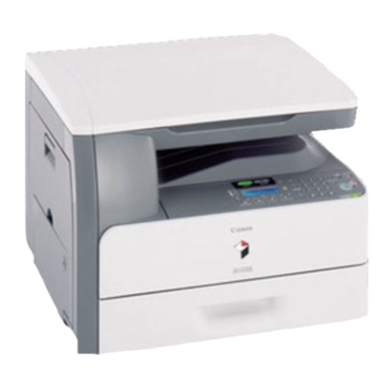
iR C1020 Series
Canon iR C1020 Series Manuals
Manuals and User Guides for Canon iR C1020 Series. We have
1
Canon iR C1020 Series manual available for free PDF download: Service Manual
Canon iR C1020 Series Service Manual (408 pages)
Brand:
Canon
| Category:
All in One Printer
| Size: 13.85 MB
Table of Contents
Table of Contents
7
Chapter 1 Introduction
19
System Construction
23
System Configuration of Pickup/Delivery Options
23
System Configuration of Print/Send Options
24
Functions of Print/Send Options
24
Product Specifications
25
Names of Parts
25
External View
25
Cross Section
26
Using the Machine
27
Turning on the Power Switch
27
Control Panel
28
User Mode Items
29
Overview
29
Paper Settings
29
Volume Settings
29
Common Settings
30
Communications Settings *3
31
Address Book Settings
33
Printer Settings
35
Timer Settings
37
Adjustment/Cleaning
38
Report Settings
38
System Management Set
39
Maintenance by the User
47
Cleaning
47
Safety
50
Points to Note at Disassembly/Assembly
50
CDRH Regulations
50
Safety of the Laser Light
50
Handling the Laser Unit
50
Safety of Toner
51
Notes When Handling a Battery
51
Product Specifications
52
Main Body Specifications
52
ADF Specifications
53
FAX Specifications
54
Function List
55
Print Speed
55
Paper Type
56
Chapter 2 Installation
57
Making Pre-Checks
61
Checking Installation Environment
61
Points to Note before Installation
61
Checking Contents
61
Unpacking and Installation
63
Unpacking
63
Installation
63
Installing Others
64
Securing Product
65
Cassette Settings
65
Points to Note When Turning off Host Machine
65
Connecting Cables
65
Auto Gradation Adjustment
66
Operation When Moving the Host Machine
66
Checking the Connection to the Network
66
Setting up the Network
66
Procedure for Ping Operation
66
Checking with Remote Host Address
67
Troubleshooting Network Connection
67
Checking with Loopback Address
67
Checking with Local Host Address
67
Checking the Images/Operations
67
Checking Image Operation
67
Installing the Card Reader
68
Notice at Installation
68
Checking the Contents
68
Turning off the Power of the Host Machine
68
Installation Procedure
68
Card ID Registration
69
Installation Procedure in the Imageware Accounting Manager (Hereinafter Referred to Iwam) Environment
70
Installing the Hand Set
70
Points to Note at Installation
70
Checking the Contents
70
Turning off the Power of the Host Machine
70
Installation Procedure
70
Installing the Memory
71
Checking the Contents
71
Checking before Memory Expansion
71
Turning off the Power of the Host Machine
71
Installation Procedure
71
Checking after Memory Expansion
72
Chapter 3 Basic Operation
73
Construction
77
Functional Configuration
77
Connecting the Main Pcbs
78
Basic Sequence
79
Basic Sequence of Operation
79
Power-On Sequence
80
Chapter 4 Main Controller
81
Overview/Configuration
85
Overview
85
Configurations/Functions
86
Set-Up Sequence
88
Overview
88
Startup Sequence
89
Image Processing
90
Overview of the Image Flow
90
Construction of the Image Processing Module
90
Reader Unit Input Image Processing
91
Compression/ Extesion/ Editing Block
91
Printer Unit Output Image Processing
92
Image Data Flow
93
Flow of Image Data According to Copy Functions
93
Flow of Image Data for the SEND Function
94
Flow of Image Data for the Fax Transmission
94
Flow of Image Data for the Fax Reception Function
95
Flow of Image Data for the PDL Function
95
Parts Replacement Procedure
96
Main Controller PCB
96
Before Removing the Main Controller PCB
96
Removing the Main Controller PCB
96
Procedure after Replacing the Main Controller PCB
96
Chapter 5 Original Exposure System
97
Basic Construction
101
Overview
101
Major Components
101
Basic Sequence
103
Basic Sequence of Operation at Power-On
103
Basic Sequence of Operation in Response to a Press on the Start Key (Book)
104
Various Control
105
Lamp Control
105
Overview
105
Enlargement/Reduction
105
Detecting the Size of Originals
106
Overview
106
Dirt Sensor Control
107
Overview
107
Stream Reading Position Shift
107
Parts Replacement Procedure
108
ADF Unit + Reader Unit
108
Before Removing the ADF Unit + Reader Unit
108
Removing the ADF Unit + Reader Unit
108
Procedure after Replacing the ADF Unit
110
Procedure after Replacing the Reader Unit
110
Reader Unit
110
Before Removing the Reader Unit
110
Removing the Reader Unit
110
Procedure after Replacing the Reader Unit
111
Chapter 6 Original Feeding System
113
Basic Construction
117
Overview
117
Basic Operation
119
Operation Mode
119
Document Size Detection
121
Detection Jams
122
Overview
122
Adf/Dadf
123
Removing the ADF Unit
123
Procedure after Replacing the ADF Unit
124
Pickup Feed Unit
124
Removing the ADF Pickup Feed Unit
124
Pick-Up Roller
126
Removing the ADF Pickup Roller
126
Separation Roller
127
Removing the ADF Separation Roller
127
Pick-Up Motor
128
Before Removing the ADF Pickup Motor
128
Removing the ADF Pickup Motor
128
Pick-Up Solenoid
129
Before Removing the ADF Pickup Solenoid
129
Removing the ADF Pickup Solenoid
129
Separation Pad
130
Removing the ADF Separation Pad
130
Chapter 7 Laser Exposure
133
Overview/Configuration
137
Overview
137
Controlling the Laser
139
Overview
139
Laser Light Emission Control
140
Laser Light Intensity Control
140
Image Masking Control
140
Failure Detection
140
Controlling the Laser Scanner Motor
141
Overview
141
Failure Detection
141
Parts Replacement Procedure
142
Laser/Scanner Unit
142
Before Removing the Laser Scanner Unit
142
Removing the Laser Scanner Unit
142
Chapter 8 Image Formation
143
Overview/Configuration
147
Overview
147
Print Process
148
Electrostatic Latent Image Formation Block
148
Development Block
150
Transfer Block
150
Fixing Block
152
Cleaning Block
152
Image Stabilization Control
153
Overview
153
Environmental Change Corrective Control
154
D-Half Control
155
Color Displacement Corrective Control
157
Auto Gradation Correction Control
159
Toner Cartridge
160
Overview
160
Toner Level Detection
161
Memory Tag Control
161
Toner Cartridge Detection
161
New Toner Cartridge Detection
162
Developing Cylinder Engagement/Disengagement Control
163
Transfer Unit
164
ETB Unit
164
Automatic Bias Control
165
ETB Cleaning
166
Transfer Roller Engagement/Disengagement Control
167
Parts Replacement Procedure
171
Drum Motor
171
Removing the Drum Motor
171
Main Drive Unit
171
Before Removing the Main Drive Unit
171
Removing the Main Drive Unit
171
Before Removing the Drum Motor
171
Point to Note When Installing the Main Drive Unit
173
Developing Estrangement Solenoid
175
Before Removing the Developing Disengage Solenoid
175
Removing the Developing Disengage Solenoid
175
Points to Note When Installing the Developing Disengage Solenoid
175
ETB Unit
176
Removing the ETB Unit
176
ETB Motor
177
Before Removing the ETB Motor
177
Removing the ETB Motor
177
ETB Estrangement Solenoid
178
Before Removing the ETB Disengage Solenoid
178
Removing the ETB Disengage Solenoid
178
Color Displacement/Image Density Sensor
179
Before Removing the Color Displacement/Density Sensor
179
Removing the Color Displacement/Density Sensor
179
Chapter 9 Pickup and Feed System
181
Overview/Configuration
185
Overview
185
Interval Speed Increase Control
187
Other Control
188
Cassette Pickup Mechanism
188
Manual Feed Pickup Mechanism
189
Skew Correction
190
Throughput-Down Control
191
Feeding Speed Control
192
Warp Control
192
Delivery
193
Detection Jams
195
Jam Detection Outline
195
Overview
195
Delay Jams
195
Pickup Delay JAM
195
Delivery Delay JAM
195
Duplexing Pickup Delay JAM
195
Duplexing Reverse Unit Delay JAM
195
Stationary Jams
196
Pickup Stationary JAM
196
Delivery Stationary JAM
196
Other Jams
196
Wrapping JAM
196
Residual JAM
196
Door Open JAM
196
Automatic Delivery Function
196
Duplex Feeding
197
Overview
197
Duplexing Feed Control
198
Duplexing Pickup Operation
201
Pickup Feed Unit
202
Before Removing the Pickup Feed Unit
202
Removing the Pickup Feed Unit
202
Cassette Pickup Roller
203
Before Removing the Cassette Pickup Roller
203
Removing the Cassette Pickup Roller
203
Pickup Motor
204
Before Removing the Pickup Motor
204
Removing the Pickup Motor
204
Cassette Pickup Solenoid
205
Before Removing the Cassette Pickup Solenoid
205
Removing the Cassette Pickup Solenoid
205
Cassette Separation Pad
207
Removing the Cassette Separation Pad
207
Manual Pickup Roller
207
Before Removing the Manual Feed Pickup Roller
207
Removing the Manual Feed Pickup Roller
207
Manual Pickup Solenoid
207
Before Removing the Manual Feed Pickup Solenoid
207
Removing the Manual Feed Pickup Solenoid
207
Manual Separation Roller
209
Before Removing the Manual Feed Separation Pad
209
Removing the Manual Feed Separation Pad
209
Duplexing Feed Motor
209
Before Removing the Duplex Feed Motor
209
Removing the Duplex Feed Motor
209
Reverse Unit
210
Before Removing the Reversal Unit
210
Removing the Reversal Unit
210
Reverse Motor
211
Before Removing the Reversal Motor
211
Removing the Reversal Motor
211
Reverse Solenoid
212
Before Removing the Reversal Solenoid
212
Removing the Reversal Solenoid
212
Chapter 10 Fixing System
215
Overview/Configuration
219
Overview
219
Various Control Mechanisms
220
Controlling the Temperature of the Fixing Unit
220
Fixing Temperature Control
220
Throughput down Control
221
Fixing Pressurizing/Release Control
222
Fixing Sleeve Pressuring/Releasing Control
222
Protection Function
223
Overview
223
Failure Detection
223
Parts Replacement Procedure
224
Fixing Unit
224
Removing the Fixing Assembly
224
Fixing Sleeve Unit
224
Before Removing the Fixing Sleeve Unit
224
Removing the Fixing Sleeve Unit
224
Fixing Drive Unit
227
Before Removing the Fixing Drive Unit
227
Removing the Fixing Drive Unit
227
Fixing Motor
230
Before Removing the Fixing Motor
230
Removing the Fixing Motor
230
DC Controller
237
Overview
237
Operation of each Block
238
Fan/Motor Control
238
Drum Motor Failure Detection
239
ETB Motor Failure Detection
239
Fixing Motor Failure Detection
239
Main Unit Fan Failure Detection
239
Duplex Fan Failure Detection
239
Control Panel
240
Overview
240
Counter
241
Overview
241
Power Supply
242
Low-Voltage Power Unit
242
Protection Function
243
Protective Function
243
Safety
243
Energy-Saving Function
243
Overview
243
Parts Replacement Procedure
245
Front Cover
245
Before Removing the Front Cover Unit
245
Removing the Front Cover Unit
245
Rear Cover
247
Right Cover
247
Left Cover
249
Before Removing the Left Cover
249
Removing the Left Cover
249
Delivery Tray Cover
250
Before Removing the Delivery Tray Cover
250
Removing the Delivery Tray Cover
250
Power Station Cover
251
Before Removing the Electrical Components Cover
251
Removing the Electrical Components Cover
251
Controller Box
251
Before Removing the Controller Box
251
Removing the Controller Box
251
Laser Scanner Cover
252
Before Removing the Laser Scanner Cover
252
Removing the Laser Scanner Cover
252
Upper Frame Unit
254
Before Removing the Upper Frame Unit
254
Removing the Upper Frame Unit
254
Operation Panel Unit
256
Removing the Control Panel Unit
256
Procedure after Replacing the Control Panel
257
NCU Board
257
Before Removing the NCU PCB
257
Removing the NCU PCB
257
DC Controller PCB
257
Before Removing the DC Controller PCB
257
Removing the DC Controller PCB
258
Procedure after Replacing the DC Controller PCB
258
Memory Controller PCB
258
Before Removing the Memory Controller PCB
258
Removing the Memory Controller PCB
258
Duplexing Driver PCB
258
Before Removing the Duplex Driver PCB
258
Removing the Duplex Driver PCB
258
Low-Voltage Power Supply PCB
258
Before Removing the Low-Voltage Power Supply PCB
258
Removing the Low Voltage Power Supply PCB
259
Cooling Fan
261
Duplex Fan
261
E-Maintenance/Imageware Remote
263
Overview
267
Scanning System
291
Procedure after Replacing the Copyboard Glass
291
Procedure after Replacing the Reader Unit
291
Fixing System
291
Checking the Nip Width (Fixing Pressure Roller)
291
Electrical Components
291
Procedure after Replacing the DC Controller PCB
291
Procedure after Replacing the Main Controller PCB
291
Procedure after Clearing RAM Data
291
Procedure after Replacing the Control Panel
292
Adf
292
Outline
292
Procedure after Replacing the ADF Unit
292
Initial Checkup
297
Initial Check
297
Test Printing
298
Outline of Electrical Components
302
Clutch/Solenoid
302
Solenoids
302
Motor/Fan
303
Motors
303
Fans
304
Sensor
305
Sensors
305
Switch
307
Switches, Speaker, and Thermistors
307
Pcbs
309
Location of Convectors
311
Location of Connectors
311
Error Code Table
321
Error Code Details
322
Jam Code
328
Jam Code (Main Body)
328
Jam Code (ADF)
328
Alarm Code
329
Alarm Code (ADF)
329
Fax Error Codes
329
Outline
329
Error Code Outline
329
User Error Code
329
Service Error Code
329
Overview
337
Preface
337
Entering the Special Management Mode
337
Menu List
338
Troubleshooting
339
Pre-Check
339
User Request
339
Paper Error
339
Image Error
339
Outline
349
Service Mode Configuration
349
Entering/Selecting Service Mode
351
Exiting Service Mode
351
Service Mode Backup
351
Service Mode Screen Operation
352
Copier
354
Display
354
DISPLAY List
354
I/O
354
R-Con
354
Adjust
354
ADJUST List
354
Function
362
Adjustment of the ACS Identification Level
364
OPTION List
364
Counter
374
COUNTER List
374
Feeder
375
Adjust
375
ADJUST List
375
Function
376
FUNCTION List
376
Fax
376
Sssw
376
SSSW List
376
Menu
377
MENU List
377
Num
378
NUM List
378
Ncu
378
NCU List
378
Testmode
382
System
382
SYSTEM List
382
Scan
383
SCAN List
383
Print
384
PRINT List
384
Fax
384
FAX List
384
Panel
385
PANEL List
385
Outline
393
Overview of Upgrade
393
Making Preparations
394
Required System Environment
394
Before Upgrade
394
Downloading System Software
395
Downloading the System Software
395
Downloading Procedure
395
Advertisement
Advertisement
Related Products
Canon iR C1021i
Canon Color iR C3480i
Canon Color iR C3080
Canon Color iR C2550i
Canon iR C2880i
Canon IRC3380Ne
Canon iR C3380i
Canon Color iR C2550
Canon Color iR C3080i
Canon Color iR C3480
Canon Categories
Printer
Digital Camera
All in One Printer
Camcorder
Scanner
More Canon Manuals
Login
Sign In
OR
Sign in with Facebook
Sign in with Google
Upload manual
Upload from disk
Upload from URL