Sign In
Upload
Manuals
Brands
Brother Manuals
Typewriter
DP-550CJ
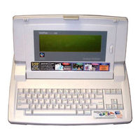
Brother DP-550CJ Manuals
Manuals and User Guides for Brother DP-550CJ. We have
3
Brother DP-550CJ manuals available for free PDF download: Owner's Manual, Service Manual, Parts Reference List
Brother DP-550CJ Service Manual (194 pages)
WORD PROCESSOR
Brand:
Brother
| Category:
Typewriter
| Size: 3.27 MB
Table of Contents
Table of Contents
2
Part Itheory of Operation
13
Fig. 1.2 General View of Printing Mechanism
15
Ink Jet Operation
16
Paper Feed Mechanism
16
Fig. 1.3A Paper Feed Mechanism
16
Fig. 1.3B Paper Feed Mechanism
17
Fig. 1.4 Paper Eject System
17
Fig. 1.5 Paper Setting System
18
Carriage Assembly
19
Fig. 1.6 Printer Flat Cable to Main PCB
19
Fig. 1.7 Printer Flat Cable to Cartridge Alignment
20
Fig. 1.8 Ink Jet Cartridge to Flat Cable Alignment
21
Carriage Motion Control
22
Fig. 1.9 Carriage Motion Control
22
Maintenance Station Operation
23
Table 1.1 Summary of Maintenance Operations
23
1.2.4.1. Spitting
24
Fig. 1.10 Print Maintenance Operation - Spitting
24
1.2.4.2. Wiping
25
Fig. 1.11 Print Maintenance Operation - Wiping
25
Capping
26
Purging
26
Fig. 1.12 Print Maintenance Operation - Capping
26
Sensors
27
1.2.5.1. Carriage Home Position Sensor
27
Fig. 1.13 Carriage Home Position Sensor
27
1.2.5.2. PE Sensor
28
Fig. 1.14 PE Sensor Mechanism
28
INK CHG (Ink Change) Functions
29
Automatic Print Head Cleaning (Purging)
29
Ink Cartridge Installation/Replacement
29
Keyboard
30
Fig. 1.15 Keyboard Assembly
30
Fig. 1.16 Key Top/Key Stem Assembly
31
Fig. 1.17 LCD Unit Installation in the Upper Cover
33
Fig. 1.18 LCD of DP-525CJ/LW-800Ic
34
Fig. 1.19 LCD of DP-530CJ/LW-810Ic and LW-810Icbl
35
Fig. 1.20 LCD of DP-540CJ, DP-550CJ/LW-840Ic
36
Chapter 1 Mechanical Theory
13
Fig. 1.1 Ink Jet Printer Assembly
13
Ink Jet Printer System Configuration
14
Ink Jet Printer
13
Chapter 2 Electrical Theory
37
System Configuration
37
Main PCB (Printed Circuit Board)
37
Switch PCB (Printed Circuit Board)
37
Keyboard FPC (Flexible Printed Circuit)
37
FDD (Floppy Disk Drive) Module
37
Fig. 2.1 Major Electronic Component Parts
38
Ink Jet Printer Configuration
39
Carriage Home Position Sensor
39
Carriage Motor
39
Ink Cartridge
39
Line Feed Motor
39
PE (Paper End) Sensor
39
Power Supply Circuit
40
Configuration
40
Fig. 2.2 Power Supply Circuit
40
Generator
41
Fig. 2.3 Timing Chart of +24V Generation Circuit
41
Fig. 2.4 Timing Chart of +5V Generation Circuit
41
Reset Circuit
42
Configuration
42
Fig. 2.5 Reset Circuit
42
CBIC and Peripherals
43
Cbic #9
43
FDC (Floppy Disk Controller)
43
Main RAM (#10, #11)
43
Main ROM (#12, #13)
43
Printer Driver Circuits (#2, #3, Q1 to Q4, and Q14 to Q17)
43
Video RAM (#7)
43
Buzzer Drive Circuit
44
Clock Circuit
44
Fig. 2.6 Buzzer Drive Circuit
44
Table 2.1 Clock Circuit
44
Country Specification Change-Over
45
Fig. 2.7 Country & Model Specification Change-Over Circuit
45
RS-232C I/F Circuit
46
Fig. 2.8 RS-232C I/F Circuit
46
Printer Control
47
Ink Jet Head Control
47
Fig. 2.9 Ink Jet Head Drive Circuit
47
Carriage Motor Control
48
Fig. 2.10 Carriage Motor Drive Circuit
48
Line Feed Motor Control
49
Fig. 2.11 Line Feed Motor Drive Circuit
49
Carriage Home Position Sensor
50
PE Sensor
50
Fig. 2.12 Carriage Home Position Sensor Circuit
50
Fig. 2.13 PE Sensor Detection Circuit
50
Switch PCB
51
Configuration
51
Fig. 2.14 External View of the Switch PCB
51
Fig. 2.15 Switch PCB Circuit
51
Keyboard System
52
FPC Operation
52
Fig. 2.16 Key/Fpc Operation
52
Keyboard Scan
53
Fig. 2.17 Electrode Wiring
53
Keyboard Control Circuit
54
Fig. 2.18 Keyboard Control Circuit
54
Fig. 2.19 Keyboard Matrix
55
Fig. 2.20 Keyboard Symbols (Corresponding to Keyboard Matrix in Fig. 2.19)
55
Fig. 2.21 LCD Display Operation Block Diagram
56
SRAM (#7) Access
57
Fig. 2.22 Example of Control Signal Timing Chart
57
Table 2.2 Table of LCD Modules
57
Fig. 2.23 LCD Drive Voltage Generation Circuit (Minus Voltage VEE)
58
Fig. 2.24 LCD Drive Voltage Generation Circuit (Plus Voltage VEE)
58
Fig.2.25 CFL Backlight Circuit
59
FDD (Floppy Disk Drive) Control
60
FDD Configuration
60
Table 2.3 FDC(#5) and FDD Module Links (Interface Signals)
60
10.2.1. Basic Operation
61
FDD Operation
61
Interface between CBIC (#8) and FDC (#5)
61
Fig.2.26 FDD Block Diagram
61
FDD Module
62
10.3.1. Read/Write Circuit
62
10.3.2. Motor Drive Circuit
62
10.3.3. Sensor Circuits
62
Part II Repair
64
Fig. 3.1 Troubleshooting Flowchart
67
Fig. 3.2 Troubleshooting Flowchart (Continued)
68
Failure Analysis
69
Table 3.1 Failure Analysis
69
Troubleshooting Tables
70
Self-Tests
77
SERIAL NUMBER Input Display
77
Fig. 3.3 Serial Number Entry Display
77
Self Print Mode
78
Fig. 3.4 Self-Print Pattern
78
Fig. 3.5 Results of Self-Print Test
80
Self-Test Mode
81
Fig. 3.6 Self-Test Menu
81
Fig. 3.7 LCD Test Menu
83
Fig. 3.8 CHECK Test Display (Magnified)
84
Fig. 3.9 CROSS Test Display (Magnified)
85
Fig. 3.10 BLACK Test Display
86
Fig. 3.11 DISP Q Test Display (Magnified)
87
Fig. 3.12 Slant Line Test Display (Magnified)
88
Print Checks
89
Print Test Pattern 1
89
Fig. 3.13 Printer Check #1 (in Progress) Display
89
Fig. 3.14 Diagram of Print Test Pattern 1
90
Fig. 3.15 Sample Print Test Pattern 1
91
Print Test Pattern 2
92
Fig. 3.16 Printer Check #2 (in Progress) Display
92
Fig. 3.17 Sample Test Pattern 2
93
7.3.2.3. Dot Patterns
94
Fig. 3.18 Dot Patterns for Print Test #2 (Patterns 1 to 4)
94
Fig. 3.19 Dot Patterns for Print Test #2 (Patterns 5 and 6)
95
Keyboard Tests
96
Fig. 3.20 Keyboard Test #1 Display
96
Fig. 3.21 Keyboard Test Key Locations
96
FDD Tests
99
FDD Test
99
Fig. 3.22 FDD Test (in Progress) Display
99
Special FDD Test
100
Fig. 3.25 Special FDD Test (in Progress) Display
101
Table 3.2 FDD Special Test Error Stage Codes
102
Table 3.3 FDD Special Test Error Codes
103
7.3.4.3. FDD SW Test
104
Fig. 3.26 Special FDD Test Display 1
104
7.3.4.4. FDD Write Error Rate Check
105
Fig. 3.27 FDD Write Error Rate Check Display
105
7.3.4.5. FDD Read Error Rate Check
107
Fig. 3.28 FDD Read Error Rate Check Display
107
PE (Paper-End) Sensor Test
109
Fig. 3.29 PE Sensor Test Start Display 1
109
Fig. 3.30 PE Sensor Test Start Display 2
109
CR (Carriage Reset) Test
110
Fig. 3.31 CR Test Start Display 1
110
Disk Type
111
Fig. 3.32 Self-Test Menu (DISK TYPE Setting)
111
RS-232C Test ("Echo Back")
112
Fig. 3.33 RS232C Echo-Back Test Start Display
112
Chapter 3 Troubleshooting
64
Introduction
64
Precautions
64
Personal Safety
64
Handling ESD-Sensitive Parts
64
Checks before Repair
65
Checks after Repair
66
Troubleshooting Flow Charts
67
Chapter 4 Component Disassembly
116
Covers
116
Fig. 4.1 Cover Assemblies
116
Upper Cover
117
Removing the
117
Removing the Upper Cover
117
Fig. 4.2 Removing the Sub Paper Support and Paper Support
118
Fig. 4.3 Removing the Top Cover
119
Fig. 4.4 Removing the Upper Cover
120
Installing the Upper Cover
122
Fig. 4.5 Removing the Core
123
Fig. 4.6 Removing the LCD Unit
124
Fig. 4.7 Removing the LCD Lower Cover
125
Fig. 4.8 Removing the LCD PCB (1)
127
Fig. 4.9 Removing the LCD PCB (2)
128
Fig. 4.10 Removing the LCD PCB (3)
129
Fig. 4.11 Removing the LCD PCB (4)
130
Fig. 4.12 Removing the LCD PCB (5)
131
Fig. 4.13 Removing LCD Latch and LCD Plate
132
Fig. 4.14 Installing LCD Latch
134
Fig. 4.15 Fitting LCD Volume Guide to LCD Volume Knob
136
Fig. 4.16 Installing the LCD Lower Cover
137
Fig. 4.17 Fitting the Core
138
Fig. 4.18 Installing the Hinge Assy
139
Keyboard Assembly
140
Removing the Keyboard
140
Fig. 4.19 Removing the Keyboard Assembly
140
Installing the Keyboard
141
Fig. 4.20 Installing the Keyboard
141
Fig. 4.21 Removing the Carrying Handle
142
Ink Jet Printer Assembly
143
Fig. 4.22 Ink Jet Printer Assembly
143
Removing the Printer Assembly
144
Installing the Printer Assembly
144
Disassembling the Printer Assembly
145
Fig. 4.23 Disassembling the Printer Assembly
145
Removing the CA Unit
146
Installing the CA Unit
146
Disassembling the PF Unit
147
Fig. 4.24 Construction of the PF Unit
147
5.3.3.1. Removing the Form
148
Fig. 4.25 Removing the Form
148
5.3.3.2. Removing the Release Lever and Release Shaft
149
Fig. 4.26 Removing the Release Lever and Release Shaft from the PF Base Assembly
149
5.3.3.3. Removing the ACF Shaft Assembly
150
Fig. 4.27 Removing the ACF Shaft Assembly
150
5.3.3.4. Removing the Pressure Rollers and Roller Holders
151
Fig. 4.28 Removing the Pressure Rollers and Roller Holders
151
5.3.3.5. Removing the Holder Plate
152
Fig. 4.29 Removing the Holder Plate
152
5.3.3.6. Removing the Hopper Assembly
153
Fig. 4.30 Removing the Hopper Assembly
154
5.3.3.7. Disassembling the Paper Feed Assembly
155
Fig. 4.31 Disassembling the Paper Feed Assembly
155
5.3.3.8. Removing the Eject Roller Assembly and the PF Roller Assembly
156
Fig. 4.32 Removing the Eject Roller Assembly and the PF Roller Assembly
156
5.3.3.9. Removing the Motor Frame Assembly
157
Fig. 4.33 Removing the Motor Frame Assembly
157
5.3.3.10. Removing the PF Stopper
158
Fig. 4.34 Removing the PF Stopper
158
5.3.3.11. Removing the PE Sensor
159
Fig. 4.35 Removing the PE Sensor
159
Disassembling the CA Unit
160
Fig. 4.36 Construction of the CA Unit
160
5.3.4.1. Removing the Carriage
161
Fig. 4.37 Printer Mechanism
161
Fig. 4.38 Removing the Carriage
162
5.3.4.2. Removing the Carriage Drive
163
Fig. 4.39 Removing the Carriage Drive
163
5.3.4.3. Removing the Star Wheel Holder Assembly
164
Fig. 4.40 Removing the Star Wheel Holder Assembly
164
5.3.4.4. Removing the MS Holder Assembly
165
Fig. 4.41 Removing the MS Holder Assembly
165
Removing the Leaf Switch (Home Position Sensor)
166
Fig. 4.42 Removing the Leaf Switch (Home Position Sensor)
166
5.3.4.6. Removing and Mounting the KB Switch Assy
167
Fig. 4.43 Removing and Mounting the KB Switch Assy
167
Adjusting the CA Unit
168
Adjusting the Carriage Home Position
168
Adjusting Belt Tension
169
Fig. 4.44 Adjusting the Belt Tension
170
Fig. 4.45 Measuring Friction During Carriage Movement
171
Removing the FDD Assembly
172
Fig. 4.46 Removing the FDD Assembly
172
Switch PCB
173
Fig. 4.47 Switch PCB
173
Removing the Switch PCB
174
Installing the Switch PCB
174
Fig. 4.48 Switch PCB
174
Removing the Main PCB
175
Fig. 4.49 Removing the Main PCB
175
Removing the Shield Plate (ESD)
176
Fig. 4.50 Removing the Shield Plate (ESD)
176
Chapter 5 Monitor Repair and Adjustment (Model Ct-1450)
177
Chapter 6 Maintenance
177
Lubrication
177
Lubricants
177
Precautions
177
Lubrication Points
177
Table 5.1 Recommended Lubricants
177
Fig. 5.1 Carriage Assembly Lubrication Points
178
Fig. 5.2 Paper Feed Assembly Lubrication Points
179
Fig. 5.3 Eject Roller Assembly and PF Roller Assembly Lubrication Points
180
Replacing the Ink Cartridge
181
Fig. 5.4 Open the Paper Support and Top Cover and Tilting the LCD to the Uprige Position
182
Fig. 5.5 Removing the Ink Jet Cartridge
183
Fig. 5.6 Removing the Protection Tape
183
Fig. 5.7 Placing the Cartridge in the Carriage
184
Fig. 5.8 Fitting the Cartridge in the Carriage
185
Cleaning the Print Head
186
Cleaning the Ink Jet Nozzles and Contacts
186
Cleaning the Print Head Automatically
186
Cleaning the Bracket Contacts (Carriage)
187
Fig. 5.9 Cleaning the Bracket Contacts
187
Appendix A Specifications
188
Electrical System
188
Printing
189
Keyboard
191
Environmental Tolerance
192
Dimensions & Weight
193
Advertisement
Brother DP-550CJ Owner's Manual (284 pages)
Desktop Publisher
Brand:
Brother
| Category:
Typewriter
| Size: 20.59 MB
Brother DP-550CJ Parts Reference List (41 pages)
Brand:
Brother
| Category:
Printer
| Size: 1.12 MB
Table of Contents
Table of Contents
3
Print Head Assembly
4
Chassis Attachments
6
Covers
10
Detector Switches
12
Ac Adapter
15
Main Pcb
16
Power Supply Pcb
20
Lcd
22
Floppy Disk Drive
24
Accessary
26
Printed Matters
28
Packing Materials
30
Keyboard Unit(List)
32
Keyboard Unit/Usa
33
Keyboard Unit/German
34
Keyboard Unit/Uk
35
Keyboard Unit/French
36
Keyboard Unit/Holland
37
Keyboard Unit/Swiss
38
Keyboard Unit/Belgian
39
Advertisement
Advertisement
Related Products
Brother DP-525CJ
Brother DP-5040CJ
Brother DP-530CJ
Brother DP-540CJ
Brother DP540CJMAIL
Brother DP550CJMAIL
Brother DP530CJMAIL
Brother DPC-8060
Brother DCP-9020CDN
Brother DCP-J562DW
Brother Categories
Sewing Machine
All in One Printer
Printer
Label Maker
Fax Machine
More Brother Manuals
Login
Sign In
OR
Sign in with Facebook
Sign in with Google
Upload manual
Upload from disk
Upload from URL