Sign In
Upload
Manuals
Brands
ABB Manuals
Measuring Instruments
COPA-XE
ABB COPA-XE Manuals
Manuals and User Guides for ABB COPA-XE. We have
1
ABB COPA-XE manual available for free PDF download: Instruction Bulletin
ABB COPA-XE Instruction Bulletin (64 pages)
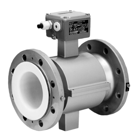
Electromagnetic Flowmeter with Pulsed DC Magnetic Field Excitation
Brand:
ABB
| Category:
Measuring Instruments
| Size: 2.68 MB
Table of Contents
Table of Contents
5
1 Flowmeter Primary and Converter Coordination
7
Data Security
7
Principle of Operation
8
Measurement Principle
8
Design
8
2 Assembly and Installation
9
Inspection
9
Flowmeter Primary Installation Requirements
9
Flowmeter Primary Installation
11
Installations in Larger Size Pipelines
12
Meter Sizes, Pressure Ratings, Flow Ranges
13
3 Programming the Converter
14
General Display Formats
14
Data Entry
15
Data Entry Instructions "Condensed Form
16
Parameter Overview and Data Entry in "Condensed Form
17
4 Parameter Entry
25
Program Protection
25
Language Entry from Table
26
Submenu Primary
26
Qmaxdn of the Meter Size at 10 M/S
26
Qmax Numeric Entry
26
Pulse Factor Forward and Reverse Numeric Entry
27
Pulse Width Numeric Entries
27
Supplementary Pulse Output Information
28
Low Flow Cutoff Numeric Entries
28
Damping Numeric Entries
28
Filter (Noise Reduction) Entry from Table
28
Density Numeric Entry
29
System Zero Numeric Entries
29
Submenu Units
29
Units Qmax Entry from Table
29
Units Totalizer Entry from Table
30
User Programmable Units
30
Units Factor Numeric Entry
30
Unit Name Entry from Table
30
Programmable Units Entry from Table
30
Submenu Alarm Entry from Table
31
Error Register
31
Setting the MAX-Alarm
31
Setting the MIN-Alarm
32
Submenu "Prog. In-/Output" Entry from Table
32
Contact Output Terminals P7, G2 (Ux, P7 for Profibus)
32
General Alarm (Errors 0 to 9, A, B) Entry from Table
32
Empty Pipe Entry from Table
32
Forward/Reverse Direction Signal Entry from Table
33
No Function
33
MAX-Alarm Entry from Table
33
MIN-Alarm Entry from Table
33
MAX/MIN-Alarm Entry from Table
33
Terminals X1/G2 (Not Available for Profibus)
33
External Zero Return Entry from Table
33
External Totalizer Reset Entry from Table
34
External Totalizer Stop
34
No Function Entry from Table
34
Submenu Current Output (Not Available for Profibus DP or ASCII Protocol)
34
Current Output Range Entry from Table
34
Iout at Alarm Entry from Table
34
Submenu Data Link
35
Communication Profibus PA
35
HART Protocol Communication
35
Communication Profibus DP / ASCII
35
Submenu Function Test Numeric Entry Only for Iout and Fout
35
Submenu "Empty Pipe Detector
36
Detector On/Off Entry from Table
36
Alarm Empty Pipe Entry from Table
37
Iout at Empty Pipe Entry from Table
37
Threshold Numeric Entry
37
Adjust Empty Pipe Detector Entry from Table
37
Submenu Totalizer
37
Reset Totalizer and Overflow Values Forward and Reverse, Preset Totalizer Numeric Entries/Entries from Table
37
Totalizer Function Entry from Table
38
Totalizer Function Standard
38
Totalizer Function Difference Totalizer
38
Submenu Display Entry from Table
38
Display 1St Line Entry from Table
39
Display 2Nd Line Entry from Table
39
Multiplex 1St Display Line Entry from Table
39
Multiplex 2Nd Display Line Entry from Table
39
Submenu Operating Mode Entry from Table
39
Operating Modes Standard/Fast Entry from Table
39
Flow Direction (Forward and Reverse) Entry from Table
39
Flow Direction Indicators Entry from Table
40
Load Data from External EEPROM
40
Store Data in External EEPROM
40
Software Version
40
TAG-Number (Instrument Address for Profibus-Communication) Numeric Entry
40
Service Code Number Numeric Entry
40
5 Error Message
41
6 Fuse Locations, Identification of the Converter Design, Ext. EEPROM Socket
42
7 Replacement Parts List
43
Replacement Parts for Converter Housing
43
Replacement Parts List (Cable Assembly)
44
Replacement Parts for Flowmeter Primary
45
8 Accuracy
46
9 Safety Relevant Section of the Instruction Bulletin
47
Grounding the Flowmeter Primary
47
Grounding Models DE21_ and DE23
48
Grounding for Flowmeters with Hard or Soft Rubber Liners
48
Signal and Excitation Cable Connections for Model MAG-XE
49
Signal and Excitation Cable Construction
49
Flowmeter Primary Connection Area
49
Electrical Connection Area
50
Installations for Protection Class IP 68
50
Interconnection Diagrams
51
Interconnection Diagram COPA-XE
51
Interconnection Diagram COPA-XE
52
Interconnection Diagram MAG-XE
53
Interconnection Diagram MAG-XE
54
Interconnection Examples for Peripherals
55
Interconnection Examples for Peripherals
56
Suppplementary Information for Connecting Profibus DP
57
Supplementary Information for Connecting Profibus PA
58
Safety Information
59
10 Start-Up
60
Initial Checks of the Flowmeter System
60
Checking the Flowmeter MAG-XE
60
System Zero Check
60
Empty Pipe" Detector (Option)
60
Converter Exchange
61
Socket Location for the Memory Module (External EEPROM)
61
Maintenance / Repair
61
Display Rotation
61
Replaceable Parts List, Flowmeter Primary
61
11 Specifications Converter for COPA-XE and MAG-XE
62
12 Overview, Parameter Settings and Designs
63
Advertisement
Advertisement
Related Products
ABB CoreSense M10
ABB Comem OLI
ABB Comem eOLI
ABB Comem DTI
ABB Comem eDTI
ABB C1952
ABB C1953
ABB CM-ENS
ABB CM-ENN
ABB CM-ENS UP/DOWN
ABB Categories
Industrial Equipment
Controller
Measuring Instruments
Battery Charger
DC Drives
More ABB Manuals
Login
Sign In
OR
Sign in with Facebook
Sign in with Google
Upload manual
Upload from disk
Upload from URL