Sign In
Upload
Manuals
Brands
ABB Manuals
Inverter
ACS355-03E-03A3-4
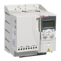
ABB ACS355-03E-03A3-4 Manuals
Manuals and User Guides for ABB ACS355-03E-03A3-4. We have
1
ABB ACS355-03E-03A3-4 manual available for free PDF download: User Manual
ABB ACS355-03E-03A3-4 User Manual (437 pages)
Brand:
ABB
| Category:
Controller
| Size: 10.29 MB
Table of Contents
List of Related Manuals
2
1. Safety
3
What this Chapter Contains
17
Safety in Installation and Maintenance
18
General Safety
19
General Safety
20
What this Chapter Contains
21
Contents of this Manual
22
Related Documents
23
Quick Installation and Commissioning Flowchart
24
Terms and Abbreviations
25
What this Chapter Contains
27
Product Overview
28
Overview of Power and Control Connections
29
Type Designation Label
30
Type Designation Key
31
What this Chapter Contains
33
Required Tools
34
Unpacking
35
Installing
36
Fasten Clamping Plates
38
What this Chapter Contains
39
Selecting the Supply Disconnecting Device (Disconnecting Means)
40
Selecting the Power Cables
41
Alternative Power Cable Types
42
Additional US Requirements
43
Selecting the Control Cables
44
Routing the Cables
45
Against Thermal Overload
46
Protecting the Motor against Thermal Overload
47
Protecting the Contacts of Relay Outputs
48
What this Chapter Contains
49
Motor and Motor Cable
50
Connecting the Power Cables
51
Connection Procedure
52
Connecting the Control Cables
53
Default I/O Connection Diagram
55
Connection Procedure
57
What this Chapter Contains
59
What this Chapter Contains
61
Starting up the Drive
62
Performing a Manual Start-Up
63
Performing a Guided Start-Up
68
Controlling the Drive through the I/O Interface
70
Performing the ID Run
71
What this Chapter Contains
75
Applicability
76
Overview
77
Operation
78
Output Mode
80
Reference Mode
81
Parameter Mode
82
Copy Mode
84
Basic Control Panel Alarm Codes
85
Assistant Control Panel
86
Overview
87
Operation
88
Output Mode
92
Parameters Mode
93
Assistants Mode
96
Changed Parameters Mode
98
Fault Logger Mode
99
Time and Date Mode
100
Parameter Backup Mode
102
I/O Settings Mode
105
What this Chapter Contains
107
Summary of the I/O Connections of the Application Macros
109
ABB Standard Macro
110
Wire Macro
111
Alternate Macro
112
Motor Potentiometer Macro
113
Hand/Auto Macro
114
PID Control Macro
115
Torque Control Macro
116
AC500 Modbus Macro
117
User Macros
119
What this Chapter Contains
121
Default Order of the Tasks
122
List of the Tasks and the Relevant Drive Parameters
123
Contents of the Assistant Displays
125
Local Control Vs. External Control
126
External Control
127
Reference Types and Processing
129
Reference Trimming
130
Example
131
Programmable Analog Inputs
132
Programmable Analog Output
133
Programmable Digital Inputs
134
Programmable Relay Output
135
Transistor Output
136
Diagnostics
137
Power Loss Ride-Through
138
Maintenance Trigger
139
Flux Braking
140
Settings
141
Critical Speeds
142
Custom U/F Ratio
143
Speed Controller Tuning
144
Settings
145
Torque Control Performance Figures
146
IR Compensation for a Scalar Controlled Drive
147
Motor Thermal Protection
148
Earth Fault Protection
149
Short-Circuit
150
Supervisions
151
Process Controller PID1
152
Settings
154
Sleep Function for the Process PID (PID1) Control
155
Example
156
Diagnostics
157
Settings
158
Control of a Mechanical Brake
159
Operation Time Scheme
160
State Shifts
161
Settings
162
Settings
164
Real-Time Clock and Timed Functions
165
Example
167
Settings
168
Counter
169
Settings
170
State Shifts
171
Example 1
172
Example 2
173
Safe Torque off (STO) Function
177
What this Chapter Contains
179
Fieldbus Equivalent
180
Differences between the Default Values in E and U Type Drives
182
Actual Signals
183
Fb Actual Signals
186
Fault History
189
Parameters
191
Reference Select
194
Constant Speeds
199
Analog Inputs
203
Relay Outputs
205
Analog Outputs
208
System Controls
209
Freq in & Tran out
215
Timer & Counter
217
Limits
222
Start/Stop
226
Accel/Decel
232
Speed Control
236
Torque Control
239
Critical Speeds
240
Motor Control
241
Maintenance Trig
247
Fault Functions
248
Automatic Reset
257
Supervision
259
Information
261
Panel Display
262
Motor Temp Meas
267
Timed Functions
269
Process Pid Set 1
273
Process Pid Set 2
282
Ext / Trim Pid
283
Mech Brk Control
285
Encoder
286
Ext Comm Module
287
Panel Comm
289
Efb Protocol
290
Fba Data out
293
Options
307
What this Chapter Contains
313
Setting up Communication through the Embedded Modbus
315
Drive Control Parameters
316
Fieldbus Control Interface
319
Fieldbus References
320
Fieldbus Reference Scaling
322
Reference Handling
323
Actual Value Scaling
324
Register Mapping
325
Function Codes
326
Exception Codes
327
Communication Profiles
328
DCU Communication Profile
333
What this Chapter Contains
339
Setting up Communication through a Fieldbus Adapter Module
341
Drive Control Parameters
342
Fieldbus Control Interface
344
References
345
Fieldbus References
346
Fieldbus Reference Scaling
348
What this Chapter Contains
349
How to Reset
350
Alarm Messages Generated by the Drive
351
Alarms Generated by the Basic Control Panel
354
Fault Messages Generated by the Drive
357
Embedded Fieldbus Faults
367
What this Chapter Contains
369
Cooling Fan
370
Capacitors
371
Control Panel
372
What this Chapter Contains
373
Ratings
374
Definitions
375
Derating
376
Power Cable Sizes and Fuses
377
Alternate Short-Circuit Protection
378
Dimensions, Weights and Free Space Requirements
381
Losses, Cooling Data and Noise
382
Noise
383
Terminal and Lead-Through Data for the Power Cables
384
Electric Power Network Specification
385
Control Connection Data
387
Brake Resistor Connection
388
Ambient Conditions
389
Materials
390
CE Marking
391
Category C1
392
UL Marking
393
C-Tick Marking
394
What this Chapter Contains
395
Frame Sizes R0 and R1, IP20 (Cabinet Installation) / UL Open
396
Frame Sizes R0 and R1, IP20 / NEMA 1
397
Frame Size R2, IP20 (Cabinet Installation) / UL Open
398
Frame Size R2, IP20 / NEMA 1
399
Frame Size R3, IP20 (Cabinet Installation) / UL Open
400
Frame Size R3, IP20 / NEMA 1
401
Frame Size R4, IP20 (Cabinet Installation) / UL Open
402
Frame Size R4, IP20 / NEMA 1
403
What this Chapter Contains
405
Selecting the Brake Resistor Cables
407
Placing the Brake Resistor
408
Start-Up
409
What this Chapter Contains
411
Installation
412
Technical Data
414
MPOW-01 Auxiliary Power Extension Module
415
Technical Data
416
What this Appendix Contains
417
Compliance with the European Machinery Directive
418
Connection Principle
419
Wiring Examples
420
Activation Switch
421
Operation Principle
422
Acceptance Test Procedure
423
Maintenance
425
Fault Tracing
426
Safety Data
427
Abbreviations
430
What this Chapter Contains
431
Start Mode
433
Product and Service Inquiries
435
Advertisement
Advertisement
Related Products
ABB ACS355-03E-38A0-4
ABB ACS355-03E-31A0-4
ABB ACS355-03E-08A8-4
ABB ACS355-03E-07A3-4
ABB ACS355-03E-05A6-4
ABB ACS355-03E-15A6-4
ABB ACS355-03E-01A2-4
ABB ACS355-03E-12A5-4
ABB ACS350 Series
ABB ACS800-104
ABB Categories
Industrial Equipment
Controller
Measuring Instruments
Battery Charger
DC Drives
More ABB Manuals
Login
Sign In
OR
Sign in with Facebook
Sign in with Google
Upload manual
Upload from disk
Upload from URL