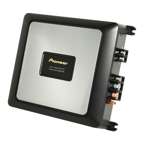
Pioneer GM-D7500M Owner's Manual
Class d mono amplifier
Hide thumbs
Also See for GM-D7500M:
- Owner's manual (36 pages) ,
- Owner's manual (84 pages) ,
- Service manual (31 pages)
Summary of Contents for Pioneer GM-D7500M
- Page 1 CLASS D MONO AMPLIFIER AMPLIFICATEUR MONO DE CLASSE D AMPLIFICADOR MONO CLASE D GM-D7500M Owner’s Manual Mode d’emploi Manual de instrucciones...
-
Page 2: Table Of Contents
Contents Before you start Information to User 3 After-sales service for Pioneer products 3 Visit our website 3 About This Product 3 Before connecting/installing the amplifier 4 Setting the Unit What’s what 5 Setting gain properly 5 Connecting the units... -
Page 3: Before You Start
Section Before you start Thank you for purchasing this PIONEER pro- U.S.A. duct. It is designed to give you many years of Pioneer Electronics (USA) Inc. enjoyment. CUSTOMER SUPPORT DIVISION PIONEER SUGGESTS USING A PROFES- P.O. Box 1760 SIONAL INSTALLER DUE TO THE COMPLEX- Long Beach, CA 90801-1760 ITY OF THIS PRODUCT. -
Page 4: Before Connecting/Installing The Amplifier
Section Before you start ! Do not allow this unit to come into contact Before connecting/ with liquids. Electrical shock could result. installing the amplifier Also, damage to this unit, smoke, and over- heating could result from contact with liquids. WARNING The surfaces of the amplifier and any attached ! Handling the cord on this product or cords as-... -
Page 5: Setting The Unit
NORMAL position. For use with an RCA unit at a high volume, set amplifier gain equipped Pioneer car stereo, with max. control to a level appropriate for the preout output of 4 V or more, adjust level to maximum output level of the head unit, so match that of the car stereo output. - Page 6 Section Setting the Unit Gain control of this unit Above illustration shows NORMAL gain set- ting. Relationship between amplifier gain and head unit output power If amplifier gain is raised improperly, this will simply increase distortion, with little increase in power. Signal waveform when outputting at high volume using amplifier gain control...
-
Page 7: Connecting The Units
Section Connecting the units Connection diagram connect the male terminal to the power term- inal via the ignition switch. 8 Speaker output terminals Please see the following section for speaker connection instructions. Refer to Connections when using the speaker input wire on the next page. -
Page 8: Connecting The Speakers
Section Connecting the units ! Install and route the separately sold battery 4 Black: Right * 5 Black: Left * wire as far as possible from the speaker wires. 6 White: Left + Install and route the separately sold battery 7 Speaker input wire with RCA pin cord wire, ground wire, speaker wires and the am- plifier as far away as possible from the anten-... -
Page 9: Connecting The Power Terminal
Section Connecting the units Connecting the power Twist the battery wire, ground wire and system remote control wire. terminal Twist ! The use of a special red battery and ground wire RD-223, available separately, is recom- mended. Connect the battery wire directly to the car battery positive terminal (+) and the ground wire to the car body. -
Page 10: Connecting The Speaker Output Terminals
Section Connecting the units 4 Terminal screws 5 Battery wire 6 Ground wire 7 System remote control wire Connecting the speaker output terminals Expose the end of the speaker wires 1 Terminal screws using nippers or a cutter by about 10 mm 2 Speaker wires (3/8 in.) and twist. -
Page 11: Installation
Section Installation Before installing the amplifier Example of installation on the floor mat or chassis WARNING Place the amplifier in the desired instal- ! Do not use unauthorized parts as this may lation location. cause malfunctions. Insert the supplied tapping screws (4 mm × ! Do not install this unit where : 18 mm) into the screw holes and push on the —... -
Page 12: Additional Information
Appendix Additional information Specifications Power output ......200 W RMS × 1 Channel (at 14.4 V, 4 W, 20 Hz to 240 Hz and ≦ 1 % THD+N) Power source ......14.4 V DC (10.8 V to 15.1 V allowable) 400 W RMS ×... - Page 13 TEL: (03) 9586-6300 PIONEER ELECTRONICS OF CANADA, INC. 300 Allstate Parkway, Markham, Ontario L3R 0P2, Canada TEL: 1-877-283-5901 TEL: 905-479-4411 PIONEER ELECTRONICS DE MEXICO, S.A. de C.V. Blvd.Manuel Avila Camacho 138 10 piso Col.Lomas de Chapultepec, Mexico, D.F. 11000 TEL: 55-9178-4270 先鋒股份有限公司...


