Advertisement
Quick Links
E/.4/RtS
OWNER'S
INSTRUCTIONS
r
Features
:or use with any 53000 SRT series garage door opener
receiver
Personalized
Code: Up to 10,000 possible combinations,
Code can easily be changed if desired
Operation:
Opener activates
when 4-code digits and
ENTER button are pressed,
The keypad will illuminate for 5 seconds at the first push of
any key If wrong numbers
are accidentally
pressed,
correction can be made immediately The ENTER key will
transmit only the last four digits,
The keypad will blink for 15 seconds after the code is
transmitte& Dudng that time you can STOP or REVERSE
door travel just by pressing the ENTER key,
The Lock feature on openers with premium door controls, is
designed to prevent operation of the door from p_dable
transmitters
However, the door will open and close from
the door control push button and the Multi-Function Keyless
Entry
Power Supply: 9 Volt battery
Programming
the Code
We recommend that you program your personal code
now, before you install the Multi-Function Keyless Entry.
Then you CaR test the reception at the mounting location
before you proceed further.
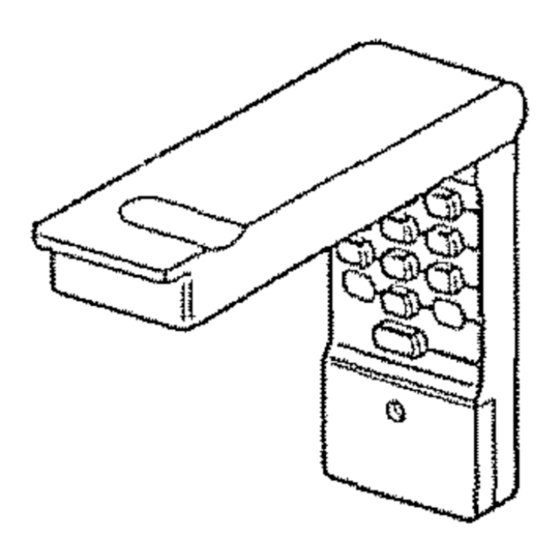
'_ Lift the cover to access the keypad, Figure 1. Decide on a
4-digit code using numbers from 0 to 9 You can use a
number more than once (for example, 4, 0, 4, 1).
2. Press the selected code digits on the keypad; then press
and HOLD the ENTER button, and press the SRT button
on the opener end panel (behind the Control Center for
screwdrive), Figure 2,
3 Depending on your opener model, when you
Figure 1
press the SRT button eitherthe opener
light(s) will flash or the garage door
will begin to move Retease the
ENTER button
The opener has now tearned the
selected code and witl respond to future keypad
commands.
To ensure that your portable remote control codes
were not disturbed while you were programming the Keyless
Entry, test your remotes and reprogram them if necessary°
To change the code In your Keyless Entry at any time,
repeat Steps 1--3.
GARAGE
DOOR OPENER
(WITH SRT BUTTON)
Green "SRT"
Button
Green thdical,3r
Figure 2
Ligh!
%
%
[]
Multi-Function
Keyless
Entry
MODEL 139.53876
To comply
with FCC rules,
adjustment
or modification
of receiver
a'ndtot]
itartsmltter
is prohibited,
except
I'or changing
the code setting and replacing the |
transmitIer
battery THERE ARE NO OTHER USER SERVICEABLE
PARTS
J
Children operating or playing with a garage door opener
can Injure themselves or others. The garage door could
close and cause serious Injury or death. Do not allow
children to operate the door push button(s) or remote
control(s).
A moving garage door could injure or klll someone under
It. Activate the opener only when you can see the door
clearly, tt is free of obstructions, and Is properly adjusted,
............
i ,,,=,,,i
i
Installation
The recommended
mounting
locations for sectional
and one-
piece doors are shown in Figure 3. You can select another
location if you preler
However,
the keypad
must be
installed
within
sight of the door.
For a one-piece
door,
use the optional
location
shown
in
the illustration
(on the edge of the door jamb) to avoid
injury
as the door swings
up and out.
Test the reception of the
Keyless Entry by
operating your opener
from the selected
location, Change the
location if necessary.
Open the keypad and
remove the battery
compartment screw and
cover to access the
bottom mounting hole
(Figure 4)
Center the keypad at
eye level against the
#..
Extedor Front Wall
1,,Piece or
Sectional Door
Doer ,Jamb Edge
',-
(Optiooal Loc_tion
Io¢ 1-Piece Door)
Door Jamb Face
SECTIONAL
DOOR ONLY
I'(EYPAD MUST BE INSTALLED
WITHIN StGHT OF THE DOOR
selected location Mark 4 1/4' up the
centedine from the bottom and drill a
t/8" pi!ot hole lnstalt top mounting
screw, aIIowJng 1/8" to protrude
above surface. Position keypad on
screw head and adjust for snug fit
With cover open so bottom mounting
hole is visible, use a punch to mark
hole. Remove keypad and drill 1/8"
pilot hole. Replace keypad and
complete installationwith bottom
screw, using care to avoid cracking
plastichousing Do not overtighten
Replace the battery cover
Battery: The 9 Volt battery should produce
power for at least one year Repface when
keypad illumination becomes dim
Figure 3
Figure 4
© ; 995 Sears Roebuck & Company
1t 4A 1970
AIt Rights Reserved
Printed in Mexico
Advertisement


