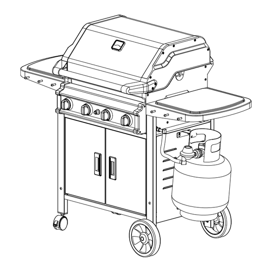
Summary of Contents for Patio Chef SS48
- Page 1 This Owner's Manual is provided and hosted by Appliance Factory Parts. Patio Chef SS48 Owner's Manual Shop genuine replacement parts for Patio Chef SS48 Find Your Patio Chef Grill Parts - Select From 14 Models -------- Manual continues below --------...
- Page 2 Owner’s Manual PATIO CHEF GAS BARBECUES FOR OUTDOOR USE ONLY This outdoor cooking gas appliance is not intended to be installed in or on recreational vehicles and/or boats. FOR YOUR SAFETY FOR YOUR SAFETY If you smell gas: 1. Do not store or use gasoline or other 1.
- Page 3 PARTS LIST A...
- Page 4 PARTS LIST B REF. DESCRIPTION Q’TY Grill Head Temperature Gauge Gasket Handle Holder Handle Bar Knob Electronic Ignition Coupling Grease Drip Tray Grease Drip Box Cart Frame Back Panel Left Side Shelf Right Side Shelf Door Upper Door Support Side Shelf Bracket Basket Regulator Assembly Tank Hook...
- Page 5 COOKING TEMPERATURES Burn-off: Before cooking on your barbecue for the first time, burn-off any residual oils or foreign matter by igniting the burners. Ensure the lid is opened, and operate at “HIGH” setting for approximately 10 minutes. Wipe with cloth to remove all residue.
- Page 6 WARNINGS Always maintain a minimum clearance of 3 feet or 1 meter from all sides of grill to any combustible construction. * Keep any electrical supply cord away from any heated surface. During assembly of grill and when attaching or replacing the L.P. gas cylinder, insure that the gas supply hose is free of kinks and is at least 3”...
- Page 7 CHECKING FOR GAS LEAKS NOTE: 1. NEVER TEST FOR LEAKS WITH A FLAME. 2. PRIOR TO FIRST USE AND AT THE BEGINNING OF EACH NEW SEASON OR WHENEVER LP GAS CYLINDER IS CHANGED, YOU MUST CHECK FOR GAS LEAKS. Follow these steps: 1.
- Page 8 TROUBLESHOOTING Problem Possible Cause Solution Burner will not light Electrode and Burner are wet Wipe dry with cloth. using ignition. Wire loose or disconnected Reconnect wire or replace ignition/wire assembly Bad igniter Replace igniter Burner will not light LP gas cylinder is empty Take LP gas cylinder to licensed With match LP gas supplier to be refilled.
- Page 9 STEP 1 Parts: 2 side frames, 1 bottom shelf and 4 male/female rivets Screw 2 side frames into bottom shelf with male/female rivets as shown. Press down the bottom shelf so that all rivets will be positioned at the upper narrow holes. Tighten all rivets. Ensure the door stopper are facing the front.
- Page 10 STEP 3 Parts: 1 back panel Install the back panel as shown. Place the slots of 2 sides of the back panel on the screws first and then slide the back panel down and tighten screws STEP 4 Parts: 4 side brackets and 4 small socket screws. Attach 2 side bracket tabs into the holes in the cart frame as shown and then secure with small socket screw.
- Page 11 STEP 5 Parts: 1 tank hook and 1 tank holder Install the slots of the tank holder and tank hook on the side panel and tighten screws. STEP 6 Parts: 1 upper door support, 2 doors and 2 baskets Insert the button on the bottom of the door into place as shown. Repeat on other side. Place the slots of the upper door support on the screws of the cart frame and then tighten screws.
- Page 12 STEP 7 Parts: 2 side shelves, 6 utensil holders, 2 small socket screw and 8 nuts Attach side shelf on the cart frame. At the front side of the side shelf, the first utensil holder must be screwed through side shelf and the side bracket. Using 1 small socket screw through the 1 hole of the rear side and the side bracket.
- Page 13 STEP 9 Parts: Grill Head, 1 coupling, 4 large socket screws and 4 nuts Tilt the grill head and position it on the cart frame as shown. Take care not to bend the main barbecue manifold inlet . Secure with large socket screw and nut. Note: Do leak test on the main barbecue manifold inlet and coupling before using the Grill.
- Page 14 STEP 10 Parts: 4 control knobs and 1 AAA battery Install the knob into the stem of the valve on control panel. Unscrew the chromed-cap on the ignition button, insert one AAA battery, assuring the positive end of the battery faces outward as shown, and screw cap back on Note: Check that the cylinder valve is closed by turning the cylinder knob clockwise to a full stop.
- Page 15 STEP 12 Parts: grease drip tray and grease drip box Slide the grease drip tray in position over the ledges under the grill head from the rear of the Grill Attach the grease drip box underneath of the grease drip tray from the front of the Grill as shown.
- Page 16 STEP 13 Parts: 1 temperature gauge and 1 gasket Attach gasket and temperature gauge on the top of the lid as shown. STEP 14 Parts: regulator assembly Hang your gas tank on the tank hook. The ring foot of the gas tank will rest on the tank holder. Attach the regulator assembly to the coupling and gas tank as shown.
- Page 17 REPAIR OR REPLACE PARTS OF THE CONTROL PANEL - Turn the burner valve OFF. - Turn the tank valve off fully. (Turn clockwise to stop.) - Detach the regulator assembly from tank valve by turning the quick coupling nut counter-clockwise. - Disconnect the coupling and regulator assembly from the inlet of the barbecue main burner manifold.

