Advertisement
Quick Links
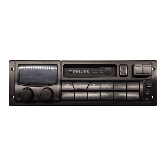
Cassette car radio 22DC501/511/521/00
22DC505/515/525/02
Service
Service
Service
O.. ak
tl
es
nee
eT
For repair information of the Cassette deck see Service
Manual of Auto Cassette Deck P6/26-1
Contents
page
Technical Data - ESD Warning
2
Controls and Connections
3
Chips Handling
4
Security Code
5
Connectors Blocks Elucidation
6
7
8
Block Diagram
-7a
Main panel PCB Layout
8a-15-15a-18-
18a
Checks and Adjustments
9
DC Voltages
10
RFD Module Schematic diagram
11 -11a
CTR Module DC501/505/511/515 Schematic Diagram
12-12a
CTR Module DC521/525 Schematic Diagram
13 - 13a
SPM Module Schematic Diagram
14-14a
Deck Module Schematic Diagram
16 - 16a
Front Part Schematic Diagram
17-17a
Power Module Schematic Diagram
19 - 19a
Detachable Unit Schematic Diagram
20
Detachable Unit PCB Layout + Mech. Partslist
20a
Exploded View
21-21a
Electrical Partslist
22 - 22a- 23-24-25
Published by Philips Car Stereo
Printed in the Netherlands
© Copyright reserved
Subject to modification
4822
725
22875
Advertisement


