Advertisement
Quick Links
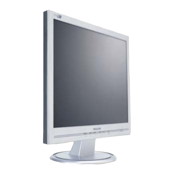
LCD Colour Monitor
Service
Service
Service
Description
Important Safety Notice -------------------------------2
Technical Data --------------------------------------3~5
Front Control & Connections-----------------------6~7
OSD menu tree ----------------------------------------8
Lock/unlock,Burn in -----------------------------------9
Factory Mode -----------------------------------------10
Pixel Defect Policy -------------------------------11~12
Mechanical Instructions-------------------------13~14
Display Adjustments--------------------------------- 15
Warning Message ------------------------------------ 16
Trouble Shooting --------------------------------17~18
Wiring Dirgram ---------------------------------------19
Block Diagram ----------------------------------------20
ANY PERSON ATTEMPTING TO SERVICE THIS CHASSIS MUST FAMILIARIZE HIMSELF WITH THE CHASSIS
AND BE AWARE OF THE NECESSARY SAFETY PRECAUTIONS TO BE USED WHEN SERVICING ELECTRONIC
EQUIPMENT CONTAINING HIGH VOLTAGES.
CAUTION: USE A SEPARATE ISOLATION TRANSFORMER FOR THIS UNIT WHEN SERVICING.
REFER TO BACK COVER FOR IMPORTANT SAFETY GUIDELINES
Published by BCU Monitors
Printed in Suzhou
170S6FB/00
150S6FB/00
170S6FB/27
150S6FB/27
170S6FG/00
150S6FG/00
170S6FG/27
150S6FG/27
170S6FS/00
150S6FS/00
TABLE OF CONTENTS
Page
Description
Scaler Schematic Diagram & C.B.A.---------- --21~26
«
Control Schematic Diagram & C.B.A ----------27~28
Power Schematic Diagram & C.B.A ------------29~42
General Product Specification -----------------43~68
Exploded View ---------------------------------------69
Spare Parts List ---------------------------------70~72
Different Parts List ----------------------------- 73~75
DDC Instruction & Data ------------------------ 76~81
Firmware upgrade for CPU -------------------- 82~83
Repair Tips --------------------------------------84~85
Safety test requirements ---------------------------86
Repair Flow Chart -------------------------------87~89
Smart Manage----- ------------------------
SAFETY NOTICE
Copyright reserved
Subject to modification
Chassis: SH6 S-Line
190S6FB/00
190S6FB/27
190S6FG/00
190S6FG/93
190S6FS/00
190S6FS/27
190S6FS/96
S
Mar .3. 2005
Page
------- 90
GB
3138 106 10448
Advertisement

Summary of Contents for Philips 150S6FB/00
- Page 1 LCD Colour Monitor Chassis: SH6 S-Line Service Service 190S6FB/00 170S6FB/00 150S6FB/00 Service 190S6FB/27 170S6FB/27 150S6FB/27 190S6FG/00 170S6FG/00 150S6FG/00 190S6FG/93 170S6FG/27 150S6FG/27 190S6FS/00 170S6FS/00 150S6FS/00 190S6FS/27 190S6FS/96 TABLE OF CONTENTS Description Page Description Page Important Safety Notice -------------------------------2 Scaler Schematic Diagram & C.B.A.---------- --21~26 Technical Data --------------------------------------3~5 «...
- Page 2 Scaler Schematic Diagram - 1...
- Page 3 Scaler Schematic Diagram - 2...
- Page 4 Scaler Schematic Diagram - 3...
- Page 5 Scaler Schematic Diagram - 4...
- Page 6 Control Board Schematic Diagram and C.B.A - 150S6/170S6 170S6/150S6...
-
Page 7: Control Board
AUTO I957 1963 spark_gap_002 1964 spark_gap_002 1965 spark_gap_002 1966 spark_gap_002 1967 spark_gap_002 STAND FOR CHIP COMPONENTS. SETNAME CLASS_NO -------- CONTROL BOARD 3138 158 6168 190S6 190B6CS/00 2005-02-04 NAME Peter V./Stella Fann SUPERS. CHECK DATE 2005-01-28 KONINKLIJKE PHILIPS ELECTRONICS N.V. 2000... - Page 8 Power Board Schematic Diagram (170S6/190S6) - Delta...
- Page 9 Power Board Schematic Diagram (170S6/190S6) - Delta...
- Page 10 Power Schematic Diagram (170S6/190S6) - Lien Chang...
- Page 11 Power Schematic Diagram (170S6/190S6) - Lien Chang...
- Page 12 Power Schematic Diagram(150S6) - Foxconn...
- Page 13 Power Schematic Diagram(150S6) - Foxconn...
- Page 14 Power Schematic Diagram (150S6) - Lien Chang...
- Page 15 Power Schematic Diagram(150S6) - Lien Chang...


