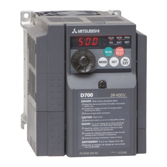
Mitsubishi Electric 700 Series Instruction Manual
Safety stop function
Hide thumbs
Also See for 700 Series:
- Training manual (271 pages) ,
- Instruction manual (242 pages) ,
- Programming manual (183 pages)
Advertisement
Quick Links
INVERTER
FR-D700-E16
Safety Stop Function Instruction Manual
1. GENERAL DESCRIPTION ............................................ 1
2. INSTALLATION AND WIRING...................................... 2
4. TEST AND CHECKING FAILURE ................................. 9
5. SAFETY PARAMETERS OF FR-D700 ......................... 10
CONTENTS
Advertisement

Summary of Contents for Mitsubishi Electric 700 Series
-
Page 1: Table Of Contents
INVERTER FR-D700-E16 Safety Stop Function Instruction Manual CONTENTS 1. GENERAL DESCRIPTION ..........1 2. INSTALLATION AND WIRING........2 3. EXAMPLE OF SAFETY SYSTEM CONFIGURATION ..5 4. TEST AND CHECKING FAILURE ......... 9 5. SAFETY PARAMETERS OF FR-D700 ......10... - Page 2 The information of this manual is merely a guide for proper installation. Mitsubishi Electric Co. cannot assume responsibility for the compliance or the noncompliance to any code, national, local or otherwise for the proper installation of this equipment.
-
Page 3: General Description
1. General description Features Mitsubishi Electric FR-D700 safety stop function prevents a drive from supplying rotational energy to motors. (In this Instruction Manual, the STO (safe torque off) function specified in IEC 61800-5-2 is referred to as the safety stop function.) Dual safety channels ‘S1’... -
Page 4: Installation And Wiring
CAUTION The following information is merely a guide for proper installation. Mitsubishi Electric Co. cannot assume responsibility for the compliance or the noncompliance to any code, national, local or otherwise for the proper installation of this equipment. A hazard of personal injury and/or equipment damage exists if codes are ignored during installation. - Page 5 Wiring The safety related terminals are described in Table.2 and Table.3 Table.2 The safety related terminals Terminal Description Rating Symbol For input of safety stop channel1. Input resistance: 4.7kΩ S1-SC is Current: 4 to 6mA Open: In safety stop mode. (In case of shorted to SC) Short: Non safety stop mode.
- Page 6 Table.3 Truth table of Safety related signals Input signal Output signal Internal safety Input power RUN-SE or A-C Inverter operation state S1-SC S2-SC circuit SO-SC (SAFE) (SAFE2) *2 *3 OFF (Open) OFF (Open) Output shutoff (Safe state) No failure OFF (Open) ON (Close) Drive enable Short...
-
Page 7: Example Of Safety System Configuration
COM1 Internal DC24V +24V Safety Circuit MITSUBISHI ELECTRIC MELSEC Safety relay module QS90SR2SN-Q FR-D700 * If the control logic is SINK logic, the common terminal is terminal SD. Fig.3 Safety system example 1 – STOP asynchronous with emergency stop button and fault detection through A-C output. - Page 8 IGBTs stop button Gate Gate Driver Driver +24V +24V COM0 COM1 Internal DC24V +24V Safety Circuit MITSUBISHI ELECTRIC FR-D700 MELSEC Safety relay module QS90SR2SN-Q R/L1 S/L2 T/L3 +24V (SAFE2) IGBTs Gate Gate Driver Driver +24V +24V FR-D700 Fig.4 Example when using multiple FR-D700 inverters for the safety stop function NOTE •...
- Page 9 IGBTs stop button Gate Gate Driver Driver +24V +24V COM0 COM1 Internal DC24V +24V Safety Circuit MITSUBISHI ELECTRIC MELSEC Safety relay module FR-D700 QS90SR2SN-Q R/L1 S/L2 T/L3 +24V (SAFE2) IGBTs Gate Gate Driver Driver +24V +24V FR-D700 * When connecting multiple inverters, use a diode on each safety input terminal to prevent a malfunction due to undesirable current.
- Page 10 COM1 Internal DC24V +24V Safety Circuit MITSUBISHI ELECTRIC MELSEC Safety relay module QS90SR2SN-Q FR-D700 * If the control logic is SINK logic, the common terminal is terminal SD. Fig.6 Safety system example 2 – STOP synchronous with emergency stop button and fault detection through RUN output.
-
Page 11: Test And Checking Failure
4. Test and checking failure CAUTION systematic To avoid faults, a test even for faulty demands of the safety function has to be performed in order to check the correct function of the monitor signal. This test shall be carried out at system installation, any software changes, parameterization changes, and/or at least once per year. -
Page 12: Safety Parameters Of Fr-D700
5. Safety parameters of FR-D700 FR-D700 safety related I/O status obeys the following truth table. Table.6 Safety parameters of FR-D700 Parameter Value 2.5x10 2.5x10 MTTF 500 years... - Page 13 REVISIONS Revision Date Manual Number Revision Aug. 2018 BCN-A211508-008-A First edition Edited Dec. 2018 BCN-A211508-008-B Compliance with the EU Machinery Directive – Functional Safety Oct. 2023 BCN-A211508-008-C Edited Functional safety standards Safety parameters BCN-A211508-008-C...
- Page 14 Mitsubishi Electric India Pvt Ltd. URL: http://www.MitsubishiElectric.in Head office Gurugram 2nd Floor, Tower A & B, Cyber Greens, DLF Cyber City, DLF Phase - III, Gurugram - 122002, Haryana, India Phone: +91-124-4630300 Fax: +91-124-4630399 Branch Office Pune Emerald House, EL-3, J Block, M.I.D.C., Bhosari, Pune - 411026, Maharashtra, India...


