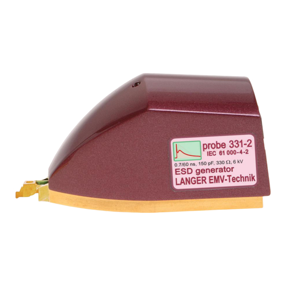
Summary of Contents for LANGER EMV-Technik P331-2
- Page 1 User manual P331-2 set ESD generator (IEC 61000-4-2) Copyright © January 2017 LANGER EMV-Technik GmbH 2021.01.24 User manual P331-2_PS_GM.doc...
-
Page 2: Table Of Contents
Reasonably foreseeable Misuse ..................8 Staff Requisition ......................... 9 Safety Instructions ......................9 P331-2 ESD Generator (IEC 61000-4-2) ..............10 Design and Function of the P331-2 probe ................ 10 Characteristics ........................11 Operational Notes ...................... 12 System Set-Up ......................13 Verifying the Waveform..................... -
Page 3: Declaration Of Conformity
1 Declaration of Conformity Manufacturer: Langer EMV-Technik GmbH Nöthnitzer Hang 31 01728 Bannewitz Germany Langer EMV-Technik GmbH herewith declares that the P331-2 set, ESD generator with P331-2, BPS 203 conforms with the following relevant regulations: - EMC Directive 2014/30/EU - Low-Voltage Directive 2014/35/EU... -
Page 4: General Information
2 General Information 2.1 Storage of the User Manual This user manual enables the safe and efficient use of the P331-2 set. It must be kept close at hand and accessible to the user. 2.2 Reading and Understanding the User Manual Read the user manual carefully, observe the safety information (Chapter 5) and follow the instructions given in this manual before putting the device into service. -
Page 5: Scope Of Delivery
DE-01728 Bannewitz LANGER mail@langer-emv.de P331-2 set EMV-Technik www.langer-emv.com 3 Scope of delivery Item Designation Type Parameter Pcs. ESD Generator (probe) P331-2 Burst Power Station BPS 203 Control software BPS 203-Client Shunt SM 02-01 0.1 R Control cable FBK 12P 1 m... -
Page 6: Technical Parameters
Internal resistance Weight 0.25 kg Sizes (L x W x H) (79 x 41 x 40) mm Table 1: P331-2 technical parameters 4.2 BPS 203 Burst Power Station 0.1 Hz – 30 Hz Frequency range Output voltage ± (0.1 ... 6) kV... -
Page 7: Sm 02-01 Shunt
DE-01728 Bannewitz LANGER mail@langer-emv.de P331-2 set EMV-Technik www.langer-emv.com 4.3 SM 02-01 Shunt DC – 3 GHz Frequency range 0.1 Ω Input resistance 50 Ω Output resistance Correction factor 26 dB Single pulse capacity 5/50 ns, 1/60 ns 360 A Table 3: SM 02-01 technical parameters... -
Page 8: Safety
5.2 Intended Use The P331-2 set is used for conducted coupling of ESD pulses into ICs. The P331-2 probe sizing orientates itself by mechanisms of the ESD coupling into electronic assemblies (according to IEC 61000-4-2 / HMM ). -
Page 9: Staff Requisition
Warning; Electricity Only connect the high-voltage cable to the P331-2 probe before operation. Don’t touch the probe tip of a P331-2 probe while it is in operation. - If insulation is damaged, the power supply has to be disconnected immediately. -
Page 10: P331-2 Esd Generator (Iec 61000-4-2)
(Figure 2). The high voltage that is needed for the pulse generation is generated in the BPS 203 and led to the HV port of the P331-2 probe via a high- voltage cable. The BPS 203 controls the P331-2 probe. The signals are led to the control cable port via a control cable. -
Page 11: Characteristics
K = 3.7 A / kV The equation reveals that the probe supplies 3.7 A per kV of the generator voltage. Note: The pulse form is only guaranteed if the P331-2 probe is operated at a minimum voltage of 200 Volt. -
Page 12: Operational Notes
DE-01728 Bannewitz LANGER mail@langer-emv.de P331-2 set EMV-Technik www.langer-emv.com 7 Operational Notes - The test set-up should always be operated via a filtered power supply. - Attention! Functional near fields and interference emissions may occur when operating EMC test set-ups. The user is responsible for taking measures to prevent any interference to the correct function of products outside the EMC environment of the test set-up (in particular through radiated interference). -
Page 13: System Set-Up
P331-2 set. The BPS 203 burst power station generates a high voltage and supplies this to the P331-2's HV input via the HV FI-FI 1 m cable. In addition, the BPS 203 also controls the P331-2 via the FBK 12P 1m control cable. The PC in turn controls the BPS 203 via the USB-AB cable. - Page 14 LANGER mail@langer-emv.de P331-2 set EMV-Technik www.langer-emv.com Figure 5: Test set-up with the P331-2 set and ICE1 set The tasks and devices listed in the table below are described in their respective manuals: Tasks and Devices Manuals Guide line IC EFT immunity (Langer EMV-...
-
Page 15: Verifying The Waveform
> 3 GHz, please note that this is limited to 3 GHz. The waveform has to be verified prior to every major measuring job. Provided the waveform does not deviate from the given parameters, the P331-2 probe only has to be calibrated every two years by Langer EMV-Technik GmbH. -
Page 16: Warranty
This document may not be copied, reproduced or electronically processed, either in its entirety or in part, without the prior written permission of Langer EMV-Technik GmbH. The management of Langer EMV-Technik GmbH assumes no liability for damage that may arise from using this printed information.
