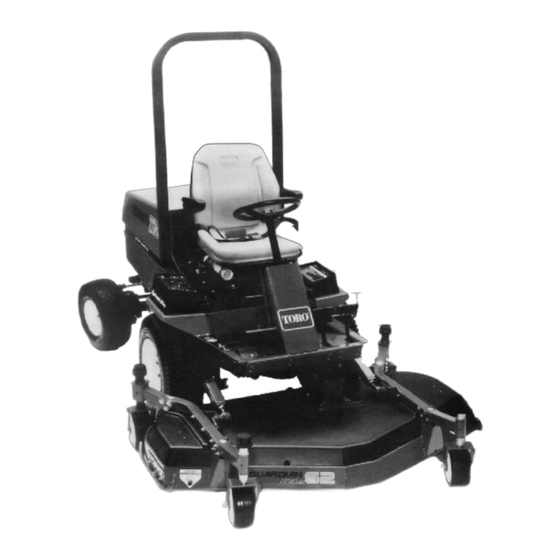
Summary of Contents for Toro Guardian 62 Recycler
- Page 1 FORM NO. 3318-404 GB Rev A OPERATOR’S 0001 MODEL NO. 30569—6 & UP MANUAL 0001 MODEL NO. 30569TE—6 & UP ® ® ® GUARDIAN 62” RECYCLER © The TORO Company 1996...
-
Page 2: Table Of Contents
Since this is a high-quality product, Toro is concerned about the future use of the machine and the safety of the user. Therefore, read this manual to familiarize yourself with proper operation and maintenance instructions. - Page 3 Safety Training WARNING—Petrol is highly flammable. • Store fuel in containers specifically designed for Read the instructions carefully. Be familiar with the this purpose. controls and the proper use of the equipment. • Refuel outdoors only and do not smoke while refueling.
- Page 4 13. Disengage drive to attachments, stop the engine, and Travel on grass slopes requires particular care. To disconnect the spark plug wire(s)or remove the igni- guard against overturning: tion key • do not stop or start suddenly when going up or •...
- Page 5 Sound & Vibration Levels If the fuel tank has to be drained, this should be done outdoors Sound Levels On multi-bladed machines, take care as rotating one blade can cause other blades to rotate. This unit has an equivalent continuous A-weighted sound pressure at the operator ear of: 90 dB(A), based on mea- When machine is to be parked, stored or left unat- surements of identical machines per 84/538/EEC.
-
Page 6: Symbol Glossary
Symbol Glossary Caustic liquids, Poisonous Electrical shock, High pressure High pressure High pressure Crushing of Crushing of chemical burns to fumes or toxic electrocution fluid, injection spray, erosion of spray, erosion of fingers or hand, toes or foot, force fingers or hand gases, asphyxiation into body flesh... - Page 7 Consult technical Fasten seat Safety alert Outline safety Read operator’s Fire, open light Eye protection manual for proper belts triangle alert symbol manual and smoking must be worn service prohibited procedures Head protection Hearing Caution, toxic First aid Flush with water Engine Transmission Hydraulic system must be worn...
- Page 8 n/min Engine start Engine stop Engine failure/ Engine rotational Choke Primer (start aid) Electrical preheat Transmission malfunction speed/frequency (low temperature start aid) N H L F Transmission Transmission Transmission Clutch Neutral High Forward oil pressure oil temperature failure/malfunction Reverse Hydraulic oil Hydraulic oil Second gear Hydraulic oil...
-
Page 9: Specifications
Specifications Width of Cut: 62 in. Height-of-Cut: Adjustable from 1-1/2” to 4-1/2” in 1/2” incre- ments. Cutter Housing: 4” deep housing is made of 12 gauge steel and reinforced with 10 gauge channel and plates. Cutting Unit Drive: Isolation mounted gear box on the cutting unit is driven by PTO shaft. -
Page 10: Adjusting Height-Of-Cut
ADJUSTING HEIGHT-OF-CUT (Fig. 2–3) The height-of-cut is adjustable from 1- ⁄ to 4- ⁄ inches in ⁄ inch increments, by adding or removing an equal number of spacers from the front and rear castor forks. The height-of-cut chart below gives the combinations of spacers to use for all height-of-cut set- tings. -
Page 11: Grease Cutting Unit
ADJUSTING THE SKIDS (Fig. 4) Adjust the skids by removing the flange nuts, positioning the skids at the desired position and reinstalling the flange nuts. GREASE THE CUTTING UNIT Before the cutting unit is operated, it must be greased: refer to Lubrication. -
Page 12: Lubrication
reasons, mow first with the height of cut at a high level; then mow again 2-3 days later with a lower height setting. ALWAYS MOW WITH SHARP BLADES—A sharp blade cuts cleanly and without tearing or shredding the grass blades like a dull blade. - Page 13 lower the cutting unit. Remove the check plug from the side of the gear box (Fig. 8) and make sure lubricant is up to the bot- tom of the hole. If the level of lubricant is low, remove the fill plug on top of the gear case and add SAE 80-90 weight.
-
Page 14: Troubleshooting
TROUBLESHOOTING... -
Page 15: Separating The Cutting Unit From Traction Unit
CAUTION • Engine could start accidentally. • Accidental starting of engine could cause serious injury to operator or bystanders. • Shut engine off and remove key from ignition switch before performing any maintenance or adjustments Figure 9 SEPARATING THE CUTTING UNIT FROM Castor arm THE TRACTION UNIT (Fig 9–11) Ball joint mount... -
Page 16: Replacing Drive Belt
in the castor arms. Secure the ball-joint mounts to the castor arms with capscrews, flatwashers and flange nuts. Position the flatwashers to the outside of the castor arm. REPLACING THE DRIVE BELT (Fig 11–13) The blade drive belt, tensioned by the stationary idler pulley, is very durable. -
Page 17: Servicing The Castor Wheels And Bearings
from side to side. If the castor spindle is loose inside the bushings, bushings are worn and must be replaced. Raise the cutting unit so its wheels are off the floor and block it so that it cannot fall accidentally. Remove the tensioning cap, spacer(s) and thrust washer from top of the castor spindle. - Page 18 (Fig 16) The blade must be replaced if a solid object is hit, the blade is out- of-balance or if the blade is bent. Always use genuine TORO replacement blades to be sure of safety and optimum performance. Never use replacement blades made by other manufacturers because they could be dangerous.
-
Page 19: Correcting The Cutting Unit Mismatch
INSPECTING AND SHARPENING THE BLADE (Fig 17–18) Raise the cutting unit to its highest position, shut the engine off and engage the parking brake. Block the cutting unit to pre- vent it from falling accidentally. Examine the cutting ends of the blade carefully, especially where the flat and curved parts of the blade meet (Fig. -
Page 20: Identification And Ordering
In any correspondence concerning the mower, supply the model and serial numbers to assure that correct information and replacement parts are obtained. To order replacement parts from an authorized TORO...


