Advertisement
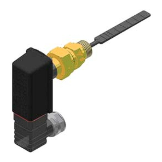
QVE1901U
Flow Switch
Description
Features
Application
Product Number
Warning/Caution Notations
Flow switch for liquids in piping 3/4-inch to 8-inch (20 mm to 200 mm) diameter
• Contact load/switching capacity:
Maximum 24 Vac, 1 A, 26 VA
Maximum 24 Vdc, 1 A, 20 W
• Nominal pressure maximum 365 psi
• Manual setting of contact type (NO/NC)
• Housing IP 65 (excluding conduit adapter)
• Maintenance-free
The QVE1901U Flow Switch is used in HVAC installations to monitor the flow of fluids
in hydraulic systems, especially in refrigeration, heat pump and heating installations (for
example: for use with condensers, boilers, heat exchangers, and so on).
QVE1901U
WARNING:
CAUTION:
Technical Instructions
Personal injury/loss of life may occur if you do not perform a
procedure as specified.
Equipment damage may occur if you do not perform a
procedure as specified.
Document No. 155-711
September 20, 2012
Siemens Industry, Inc.
Advertisement
Table of Contents

Summary of Contents for Siemens QVE1901U
- Page 1 • Maintenance-free Application The QVE1901U Flow Switch is used in HVAC installations to monitor the flow of fluids in hydraulic systems, especially in refrigeration, heat pump and heating installations (for example: for use with condensers, boilers, heat exchangers, and so on).
-
Page 2: Mechanical Design
Technical Instructions QVE1901U Flow Switch Document Number 155-711 September 20, 2012 Mechanical Design Reed Contact (3) The device records the flow of monitored medium via a paddle system (1), which has a permanent magnet (2) attached at its upper end. A reed contact (3) is positioned Magnet (2) outside the flow above this magnet. -
Page 3: Engineering Notes
QVE1901U Flow Switch Technical Instructions Document Number 155-711 September 20, 2012 • On site: Engineering Notes – A T-junction with a female-threaded (1/2" NPT) fitting is required for 3/4” to 2” line sizes. – A 1-inch, female-threaded (1/2” NPT) welding socket is required for 3" to 8" line sizes. - Page 4 Technical Instructions QVE1901U Flow Switch Document Number 155-711 September 20, 2012 Line Size 3/4-inch to 8 inches (20 mm to 200 mm) Nut size 27 external thread 1/2-14 NPT Welding adapter with female thread 1/2-14 NPT, adapter length 1’’ Figure 4.
- Page 5 QVE1901U Flow Switch Technical Instructions Document Number 155-711 September 20, 2012 Elbow Plug Connector EN 175301-803-A Figure 5. Figure 6. Figure 7. Figure 8. • Loosen the central screw M3×35 and disconnect the cable socket from the connector . See Figure 5. Pull the central screw out of the cable socket •...
- Page 6 Technical Instructions QVE1901U Flow Switch Document Number 155-711 September 20, 2012 Adjust Switching The switching unit of the control switch enables two contact types: Unit 1. Make contact (normally open): RED arrow on the switching unit Standard Contact 2. Break contact (normally closed):...
-
Page 7: Specifications
QVE1901U Flow Switch Technical Instructions Document Number 155-711 September 20, 2012 Field of use Specifications Suitable media water and water/glycol mixture Functional data Piping diameter 3/4-inch to 8-inch (DN 20 to 200) Type of switch Reed contact Maximum contact voltage... - Page 8 Information in this publication is based on current specifications. The company reserves the right to make changes in specifications and models as design improvements are introduced. Product or company names mentioned herein may be the trademarks of their respective owners. © 2012 Siemens Industry, Inc. Siemens Industry, Inc.


