Table of Contents
Advertisement
Advertisement
Table of Contents

Summary of Contents for Sharp RZ-E601
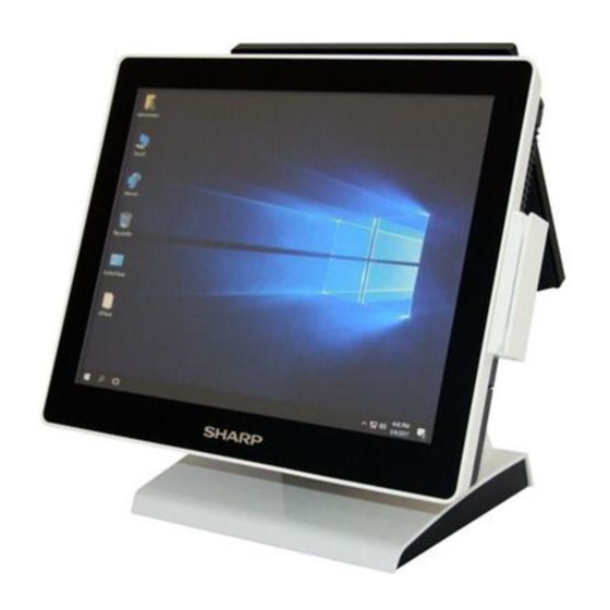
- Page 1 Sharp AIO POS RZ-E601 RZ-E701 Service Guide Release Version 0.2 Dec, 2017...
-
Page 2: Table Of Contents
Sharp AIO POS Table of Contents Assignment & Jumper Setting ..........3 Motherboard Placement ..............…3 Motherboard I/O Ports ..............4 POS Touch I/O Ports…..............4 Assignment Special Pin Connector ..........5 I/O Connector ................5 Jumper Setting ................6 Holder Pin Assignmentn .............. -
Page 3: Pin Assignment & Jumper Setting
Pin Assignment & Jumper Setting Motherboard Placement... -
Page 4: Motherboard I/O Ports
Motherboard I/O Ports... -
Page 5: Special Pin Assignment Connector
Special Pin Assignment Connectors Connector Note Pin 1 is selected by BIOS for COM1 and COM2 Pin Assignment Connector MPCIE1 Note miniPCIe / mSATA functions are selected by JMPCIE1 Pin Assignment... -
Page 6: Jumper Setting
Jumper Setting Jumper location CMOS1 Setting drawing & descriptions Jumper location JCD1 Setting drawing & descriptions Jumper location JMPCIE1 Setting drawing & descriptions Jumper location JLVDS1 Setting drawing & descriptions... - Page 7 Jumper location JCOM5 Setting drawing & descriptions...
-
Page 8: Holder Pin Assignmentn
2. Header Pin Assignment Header location BKL1 Setting drawing & Pin definition Pin # descriptions Ground LCD_BL_EN BL_PWM Control Ground Function Panel’s backlight connector. Header location SATA_PWR1 Setting drawing & Pin definition Pin # descriptions Ground Ground VCC5 Function Supply SATA power 5V and 12V. Header location H_USB1, H_USB2, H_USB3 Setting drawing &... - Page 9 Header location TOUCH1 (for RZ-E601) Setting drawing & Pin definition Pin # descriptions SENSE Function R-Touch header Header location COM5 Setting drawing & Pin definition Pin # Pin definition Pin # descriptions Ground Function Internal COM header Header location (for RZ-E701) Setting drawing &...
- Page 10 Header location LVDS1 Setting drawing & descriptions Pin # Pin definition Pin # Pin definition Ground Ground LVDSA_DATA0N LVDSA_DATA1N LVDSA_DATA0P LVDSA_DATA1P Ground Ground LVDSA_DATA2N LVDSA_CLKN LVDSA_DATA2P LVDSA_CLKP Ground Ground LVDSA_DATA3N LVDSB_DATA0N LVDSA_DATA3P LVDSB_DATA0P Ground Ground LVDSB_DATA1N LVDSB_DATA2N LVDSB_DATA1P LVDSB_DATA2P Ground Ground LVDSB_CLKN LVDSB_DATA3N...
-
Page 11: Basic Trouble-Shooting
BASIC TROUBLE-SHOOTING TROUBLE SHOOTING Trouble-shooting Item Failure Symptom Trouble-shooting 1. 1. Verify that the 19V Power adapter is connected to the unit System no boot, Power LED 2. Replace 19V Power Adapter 3. Replace Motherboard System no boot, continuous 1. Verify that RAM is inserted properly abnormal beeping sound 2. -
Page 12: System Preparation For Trouble-Shooting
SYSTEM PREPARATION FOR TROUBLE-SHOOTING 1.0 Removal of Stand, HDD, and Rear Cover 1.1 Release the thumb screw and remove the stand from system unit. 1.2 Remove HDD 1.3 Remove Rear Cover screws... - Page 13 2.0 LCD panel replacement 2.1.1 Remove PCAP touch FPC tail (RZ-E701) 2.1.2 Remove Resitive touch FPC tail (RZ-E601/E606/E606SC) 2.2 Remove screws 2.3 Remove panel screws...
- Page 14 3.0 PCBA replacement 3.1 Remove heat sink 3.2 Remove cables 3.3 Remove screws and RAM...
-
Page 15: Peripherals Installation Guide
Peripherals Installation Guide VFD installation guide (model name : RZ-E1DP1) 1. To Connect POS and VFD cables (be careful the cables colour that are connected should be matching ) Insert cable into POS hole Lock 4pcs screws... -
Page 16: Msr+ Ibutton And Msr (For Jp) Installation Guide
MSR+ iButton and MSR (for JP) (model name : RZ-E1MT1) (model name : installation guide RZ-E1MR2) (on POS Right side) 1. Connecting POS and MSR( slim)+ iButton cable (2 bundles) (be careful the cable colours that are connected should be matching ) 2. - Page 17 Lock screw 2 pcs Assemble COVER...
-
Page 18: Msr Installation Guide
MSR Single head (Slim type) installation guide (on POS Right side) ( Model name : RZ-E1MR1 ) Insert cable into POS hole Note that the grounding wire position should not exceed the lower edge of this line, otherwise it will affect the assembly Connecting POS and MSR cable (be careful the cable colours that are connected should be matching ) Insert cable into POS hole... - Page 19 fixing clip Lock screw 2 pcs Assemble MSR COVER...
-
Page 20: 2Nd Display Installation Guide
2nd display installation guide (model name : RZ-E1DP3) 1. Bend stand cover frame and remove it 2 After removing stand cover frame 3 cable routing... - Page 21 4. M4 screw *4pcs 5. cable routing and m3 screw *4pcs...
- Page 22 6 plug in I/O connector...
- Page 23 7. cable routing with Stand cover stand cover...
- Page 24 8.Put the cushion on RZ-E1DP3(To avoid to pinch a hand) Move the hinge of RZ-E1DP3 to back side. Hinge Fit to center Cushion Fitting line Fitting line (Upper edge of hinge plate) Hinge Plate...
- Page 25 Cushion (Note) -Remove dust on putting surface. -Fits the upper edge of cushion to the upper edge of hinge plate. -Puts the cushion.
-
Page 26: Bios Update Procedure
RZ-601: BIOS update procedure BIOS setting choice boot to “UEFI: Built-in EFI Shell” 1. Make sure the Sharp SKU name is match to BIOS file name. (RZ-E601: ME70AA15.C4B) 2.Ensure that the USB-key include afuefix64.efi and BIOS bin file. 3.Type “fs0:” to entry USB-Key. - Page 27 RZ-E701: BIOS update procedure BIOS setting choice boot to “UEFI: Built-in EFI Shell” 1. Make sure the Sharp SKU name is match to BIOS file name. (RZ-E701: ME70AA15.C4D) 2.Ensure that the USB-key include afuefix64.efi and BIOS bin file. 3.Type “fs0:” to entry USB-Key.


