Advertisement
❶
Select the mounting location.
Mounting Location Guidelines
• 2.3 m mounting height.
• Avoid direct or reflected sunlight.
• Aim sensor away from windows, heating/cooling devices
or large moving objects.
• Sensor must have a clear line-of-sight to protected area.
❹
Wire the unit.
• Connect wires as shown using 0.2 - 1.3 mm
2
wire size.
Observe proper polarity.
• If not using the integrated EOL resistors, remove jumpers from
all pins.
• If using the integrated EOL resistors:
1. Connect the sensor to the panel (see wiring diagrams on
the right; if using the two loop option, also cut link W1).
2. Place the jumpers on the appropriate fault, tamper and
alarm pin options (see table below).
Notes:
• Consult the Control Panel manual to determine proper EOL
selection.
• Fit only one jumper each for the fault, tamper and alarm
EOL settings.
Jumper Position EOL Value
FAULT
E
2.2K
(RF)
F
3K
A
1K
TAMPER
B
2.2K
(RT)
C
4.7K
D
5.6K
1K
A
Factory default
2.2K
B
settings are
ALARM
shown in grey.
(RA)
4.7K
C
D
5.6K
❷
Separate the sensor housings and remove the
printed circuit board (PCB).
For improved anti-mask
performance the look-down
mirror is disabled. To enable
look-down remove the mask.
• Use a small screwdriver to unfasten the housing latch. Gently pull
apart the housings.
• Push outward on the PCB latch and lift the PCB out of the housing.
❺
Fault, Alarm and Tamper configured to one loop.
Fault, Alarm and Tamper configured to two loops.
❸
Mount the unit.
Rear Tamper Breakaway
Tab: Best if mounted to a
Note: The cover screw,
stud, solid wood, or with
when used, is installed
a robust wall anchor.
here.
*Note: If the Rear
Tamper function is not
required, do not use the
mounting holes in the
Rear Tamper Breakaway
Tab.
• Slide the wire through the wire channel in the back housing.
• Mount the back housing flat against a wall or in a corner.
• Replace the PCB.
Walk-test the sensor.
a
50%
75%
100%
25%
• Apply power to the unit. Initialisation is complete when the
LED stops flashing slowly.
• Adjust the microwave range to minimum setting (25%) by
turning the range adjustment counterclockwise using a
small screwdriver.
• Replace the front housing.
• Begin walking through the detection area.
- The LED will turn red, indicating an alarm detection.
• Increase the microwave range as necessary.
• Repeat the items in step 5a until proper detection range is
obtained.
• The sensor MUST be walk tested after every power up
to complete the power up mask detection test.
Corner
Mount Hole*
Wall
Mount
Holes
Wire Channel
Note: If using the Rear Tamper feature, refer to the Rear Tamper
section before mounting the sensor.
❺
Optional: Walk-test using Zone Finder.
b
Use the Zone Finder mode to identify the PIR and/or
microwave pattern. In Zone Finder mode the red
LED is disabled.
• Use a screwdriver to short the test pads.
• During the Zone Finder walk-test mode, the LED turns:
- green for one second for every PIR detection;
- yellow for two seconds for every microwave detec-
tion.
• Adjust the microwave range as necessary.
• Zone finder mode times out after ten minutes.
Corner
Mount
Holes
Advertisement
Table of Contents

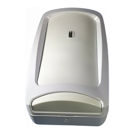
Summary of Contents for Honeywell DT7550UK2 DUAL TEC
- Page 1 ❶ ❷ ❸ Select the mounting location. Separate the sensor housings and remove the Mount the unit. printed circuit board (PCB). Rear Tamper Breakaway Tab: Best if mounted to a Note: The cover screw, stud, solid wood, or with when used, is installed a robust wall anchor.
- Page 2 11.9 cm H x 7.1 cm W x 4.2 cm D © 2008 Honeywell International Inc. • Honeywell, IntelliSense and DUAL TEC are registered trademarks of Honeywell International Inc. All other trademarks are the properties of their respective owners. All rights reserved.


