Advertisement
Table of Contents
E529 Smart Digital Thermostat Product Guide
Table of Contents
Rev 2.0 3/20/2017
Table of Contents .............................................. Page 1
Overview and General Concept ......................... Page 2
Application ......................................................... Page 3
Features ............................................................ Page 4
LCD Item Descriptions ....................................... Page 5
Back and Bottom Features ................................ Page 6
Wireless Communication ................................... Page 6
Installation ......................................................... Page 7
Placement.......................................................... Page 7
Mounting Instructions ........................................ Page 7
Technical Specifications .................................... Page 8
FCC Statement .................................................. Page 8
Document Revision History ............................... Page 9
E529 Product Guide
1
Advertisement
Table of Contents

Summary of Contents for Honeywell E529
-
Page 1: Table Of Contents
E529 Product Guide E529 Smart Digital Thermostat Product Guide Table of Contents Table of Contents ..........Page 1 Overview and General Concept ......Page 2 Application ............Page 3 Features ............Page 4 LCD Item Descriptions ........Page 5 Back and Bottom Features ........ Page 6 Wireless Communication ........ -
Page 2: Overview And General Concept
PC502.4G. Appendix 4 shows typical installations using the E529.4G. Figure 1 below shows a typical E529.4G installation. Since the E529.4G has a user interface, it can also be used to configure in- room devices that do not have a user interface such as an X47, PC502.4G or X07.P. -
Page 3: Application
E529 Product Guide Application In its most basic form, the battery powered e529 functions as a programmable DDC thermostat, automatically adjusting fan speeds and valves to achieve set temperature (Note: Guests can manually select heat or cool by pressing the OFF/AUTO button and cycling through OFF, AUTO, HEAT and COOL). -
Page 4: Features
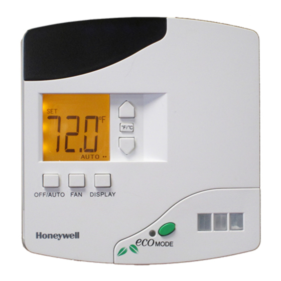
(HI). The fan speed cycle begins again with the next push DISPLAY: Cycles the LCD between the Set (selected) Figure 2. E529.4G Front Button temperature and the measured Room temperature. [Outdoor and Features Description temperature may also be displayed if the system is networked to a server or the Web broadcasting readings from an outside sensor.]. -
Page 5: Lcd Item Descriptions
DOES NOT currently work if using a CBL32 Room Gateway such as an E528.4G or PC502.4G. You will NOT get a Dot on the E529 display. You must use the E529 rUn2 WAN Test to check that the room is connected to the network 7. -
Page 6: Back And Bottom Features
1. Battery Compartment: Holds 4 AA Alkaline Batteries 2. Programming Header: Provides the ability to upload new software to the E529.RF to upgrade features [NOTE: Used exclusively at the factory] 3. Light Sensor: Detects level of light in the room to be used for energy management 4. -
Page 7: Installation
4. Verify that the E529.4G display is now showing information. At power ON (ie inserting the 4 AA batteries), confirm all segments and characters are displayed on the E529 LCD display. If the display is blank, verify that the Rev 2.0 3/20/2017... -
Page 8: Technical Specifications
You will be configuring the actual Room ID and other required parameters into the E529.4G later. 5. Hook the tabs at the top rear of the E529.4G housing into the matching depressions at the top of mounting plate and rotate the bottom of the E529.4G housing toward the wall until it snaps into the place on the... -
Page 9: Document Revision History
The material in this document is for information purposes only. The content and the product it describes are subject to change without notice. Honeywell makes no representations or warranties with respect to this document. In no event shall Honeywell be liable for technical or editorial omissions or mistakes in this document, nor shall it be liable for any damages, direct or incidental, arising out of or related to the use of this document.


